Old ‘blog entries – building the Industrial Garratt locomotive (2011 entries)

Actually, this is a tale which goes back to before the coulshed.com website existed, and then the website changed (at the beginning of 2012), so I am reconstructing the entries from before January 2012, in order.

Painted and airbrush weathered from above

Click on any picture to enlarge it !

The start of making my model industrial 0-4-0+0-4-0 Beyer-Garratt in Scale Seven goes back to the middle of 2010.  The kit was a decade in my cupboards waiting for me to summon the courage to tackle four sets of valve gear, never having constructed a model with valve gear before!  The kit was a very basic one, designed for Finescale, “0-gauge”, and I decided to make it with near true scale-width frames, as well as the rest of S7 standards.

This meant that my first difficulty was to adapt the spacers for the driving-unit frames.  The kit had “fold-up” frames, held also at the desired width by the buffer-beams and spacers on the inside end of the driving units.

Frames with scoring BandWI was also planning to fit suspension to every axle, so slots to accept the suspension unit had to be cut in the frames themselves.  

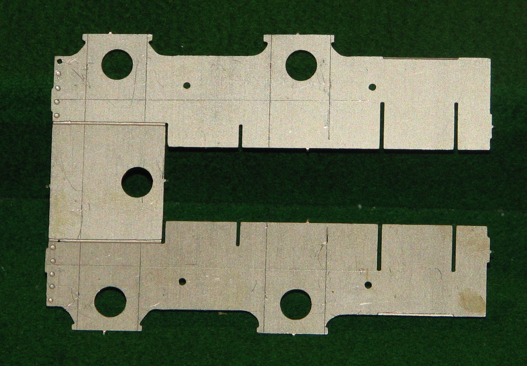
This picture shows the flat fold-up frames with the scored markings to cut out the wide slots for the suspension units.  The actual frames are seen above and below a horizontal plate, with the original axle holes about to be cut out.


Cylinder end plate with extra cuts

The buffer-beams and other spacers had to have new slots cut into them at the new width (29mm).


Cylinder end spacers adapted cropped


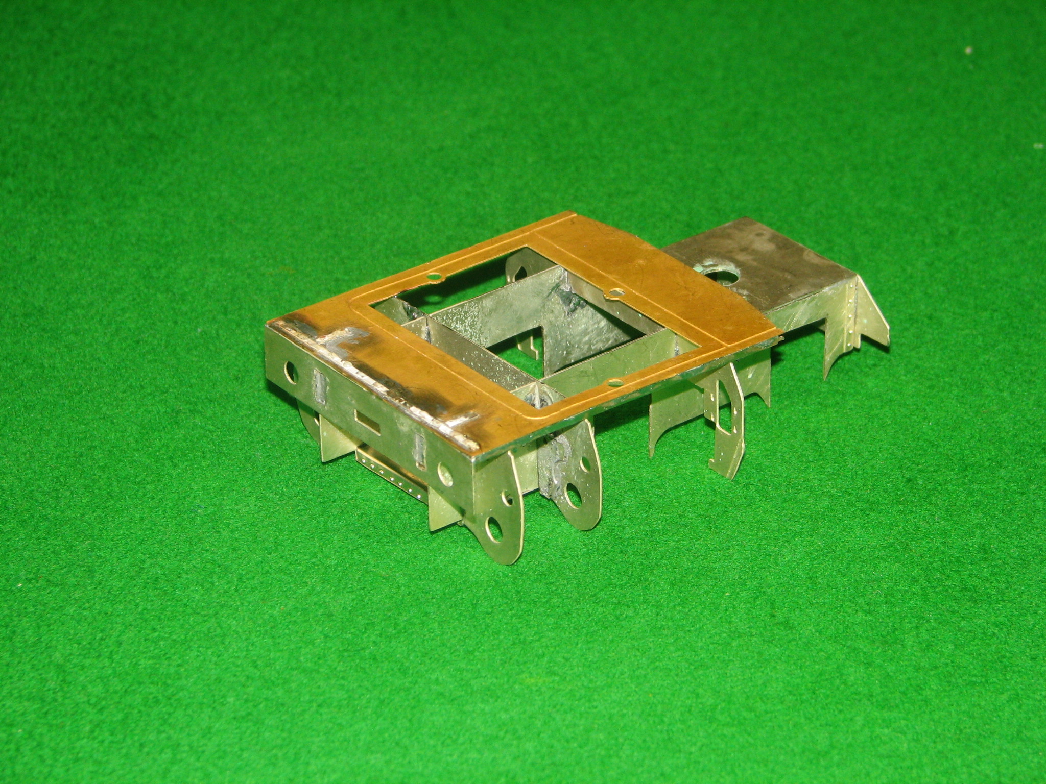
In the end the slots were just widened and scrap brass added to set the width of the frames, as shown.


Frames upside down to show the slots for the suspension units

Frames upside down to show the slots for the suspension units


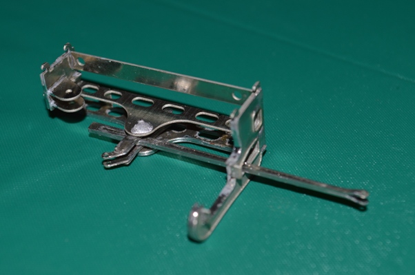
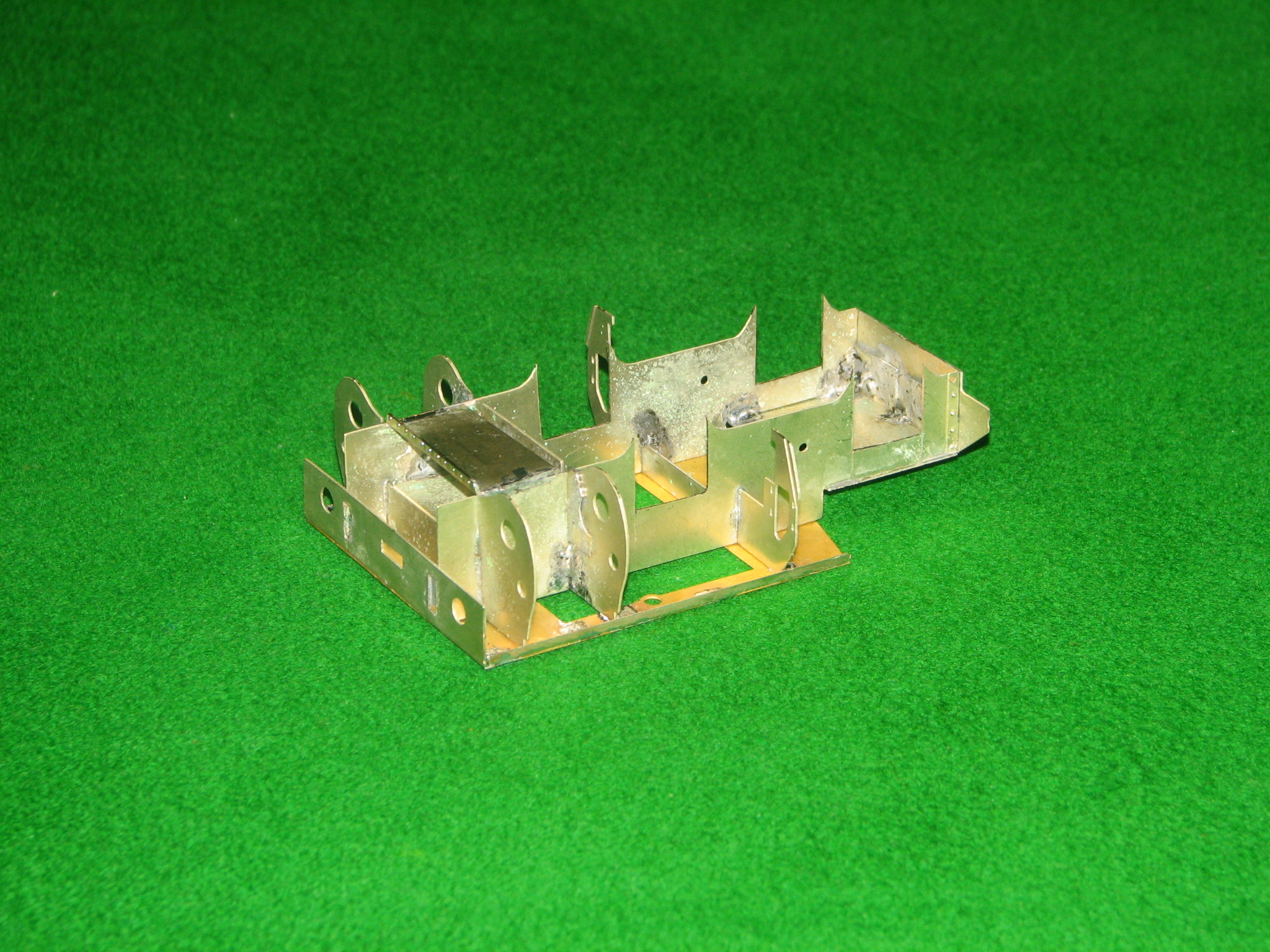
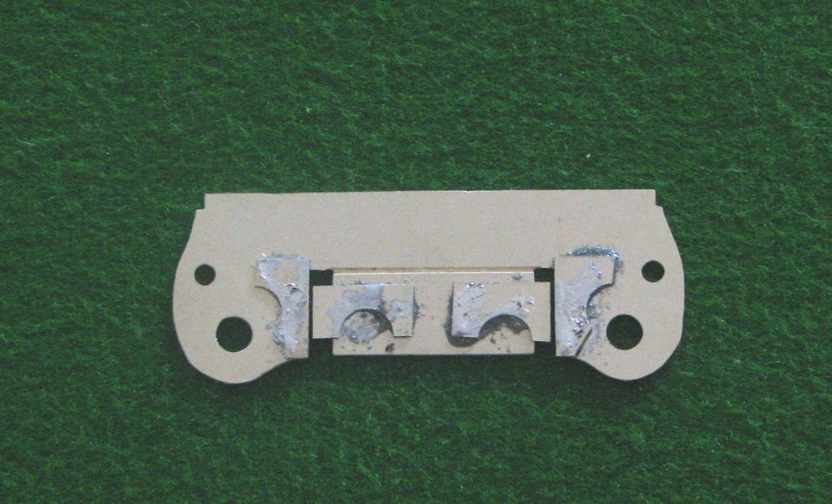
This was all very worrying, as it appeared to be a very destructive approach to kit-building!  Fortunately all the calculations appeared to be working when I assembled the frames, as shown.


Front driving unit, from the front.

Front driving unit, from the front.


If you look carefully it is possible to see where the buffer-beam slots have been widened for the scale-width frames.


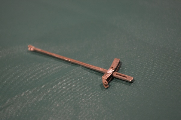
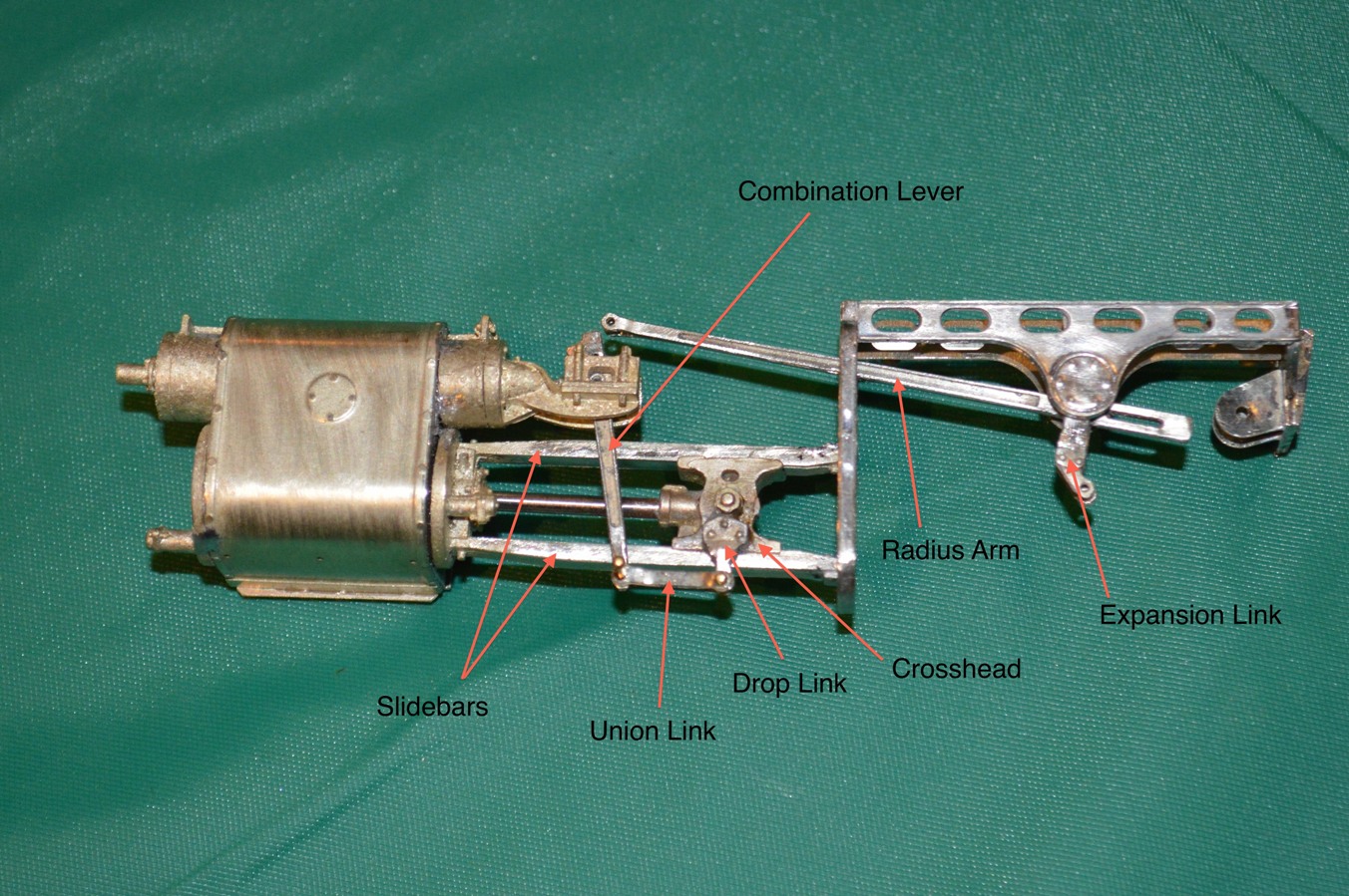
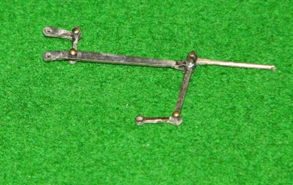
There then ensued a long struggle with the suspension units, the wheels, the “plunger” pick-ups and the coupling rods, just to get the units to move under their own power.

So many times I wondered if it was beyond me ….

This takes us up to the start of 2011, and the start of our website.  The valve gear was yet to be done.

April 2011
Connecting rod state 2 smallI should be able to put together some more of my model Garratt locomotive – an 040+040 industrial steam engine.  Here’s a picture of the front end driving unit as so far built.  The trouble building this to exact scale dimensions (Scale Seven) is a story in itself ….Valve gear rods smallLooking after (ie staying in the house at the same time) as the two boys has some advantages: I took some time to construct some more of my Garratt.

Here’s my first ever construction of outside valve gear for a model steam engine – and it moves !
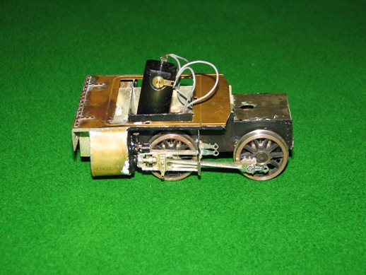
  Valve gear in place from the rear smallWhat makes it difficult is to make the joints all move.  On the assembly shown below there are five joints made with brass pins soldered to etched brass valve gear “rods”.  the pins are about 0.8mm diameter, 5mm long, and clearly the solder only has to fix the pin to one rod, and not the other.  There are about ten joints like this for each set of valve gear – and there are four sets.
I’m very proud to have successfully complete one!Front tank from rear smallBunker from front small


June 2011

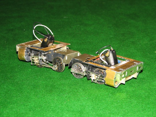
As you can see, both sets of driving wheels are now complete with coupling and connecting rods, plus valve gear.
Valve gear completed 4 s Valve_gear_completed_3_s
If only I could put moving pictures on the website, I could proudly demonstrate how it all moves and proceeds along the track!


Front_driving_unit_partially_complete_1_s
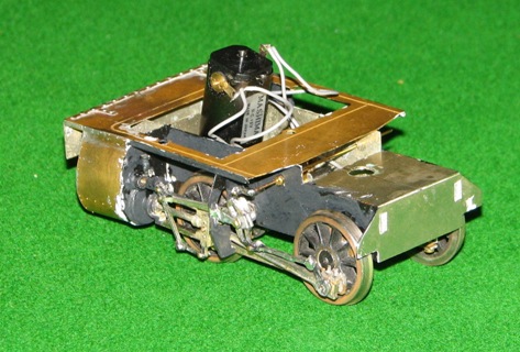
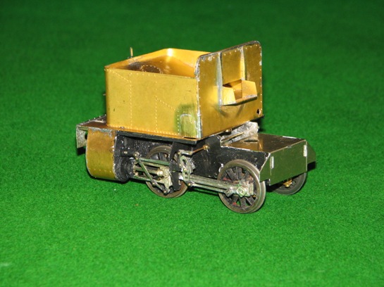
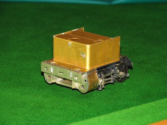
I have now fitted the bunker and the water tank onto the diving wheel assemblies of my model Garratt locomotive ….

Rear driving unit partially complete 3 s


October 2011

Smallpic_Both_drive_units_nearly_finished
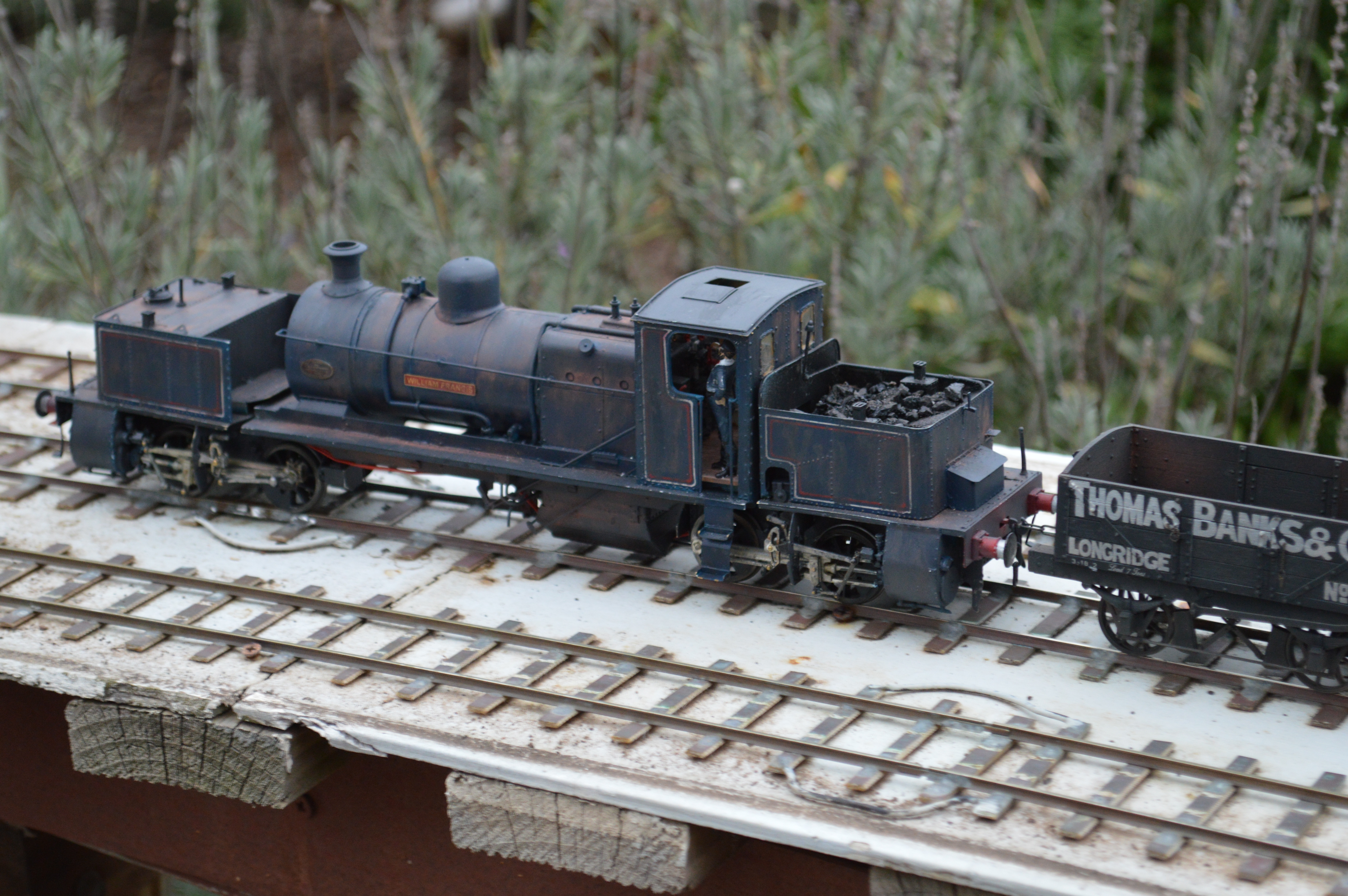
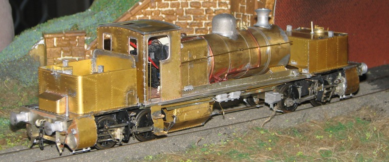
My model of the industrial Garratt “William Francis” is coming along quite well, now.

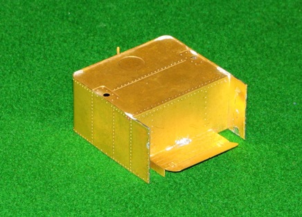
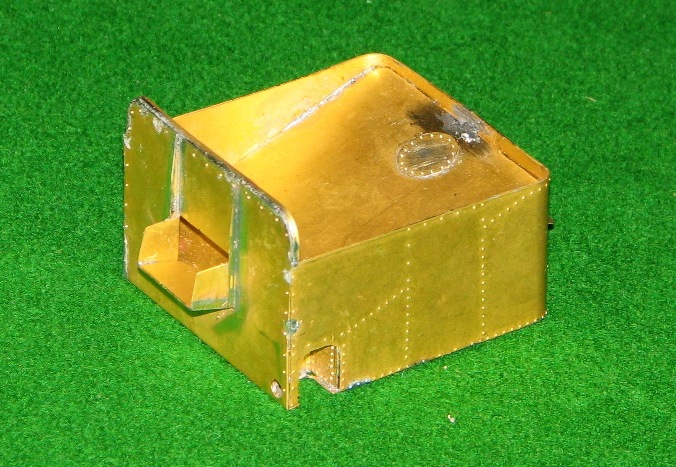
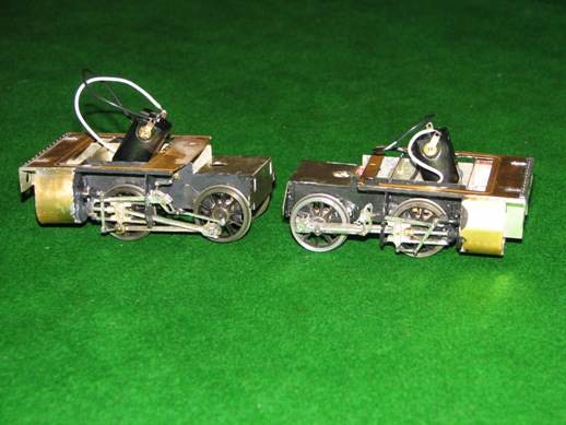
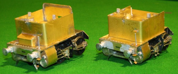
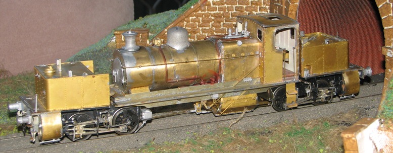
The first picture is of the two end units, with the rear one containing the coal bunker on the left and the front unit with a water tank on the right.

Smallpic Central unit nearly finished
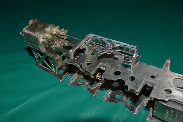
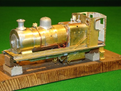
This is the central unit, with the boiler and cab.
It’s a very complicated model, and the kit (originally bought by me over a decade ago), is far from perfect or comprehensive.  It’s really just a starting point for building a model of this industrial locomotive – adding detail is very much needed.  However that is the part which I enjoy most, so that is certainly OK by me.

November 2011

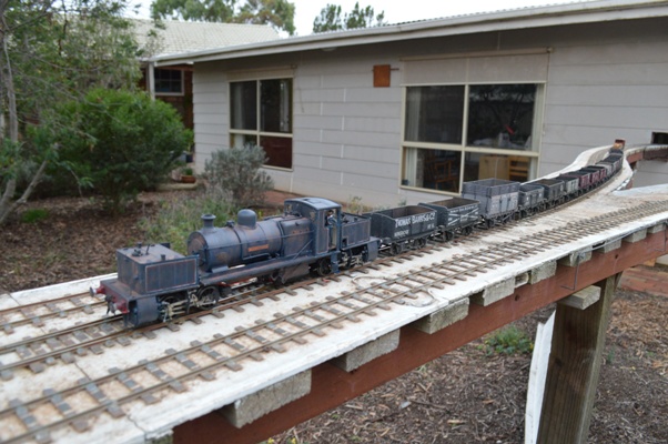
My Garratt.  It’s an 0-4-0+0-4-0 locomotive.  The prototype ran in an industrial complex centred around a large coal mine in Warwickshire.  It’s taken me a year to get this far, being quite a complex project.  Here you are, though.  Just three minor details to go (nameplates and a clack valve on the right hand side of the boiler).

Almost finished 3 small

Almost finished 2 small

Almost finished 6 small

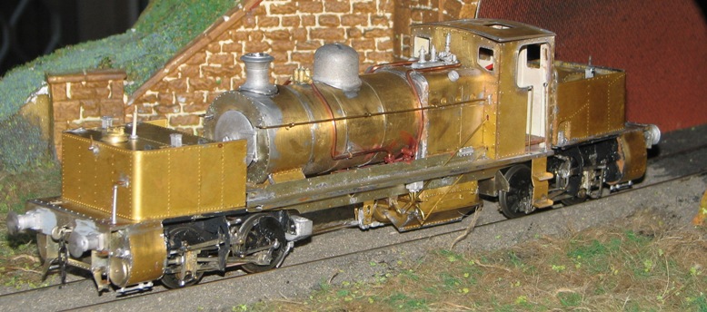
Then it will be on to the painting …

December 2011

So what have I been doing?

Primer Right lateral small
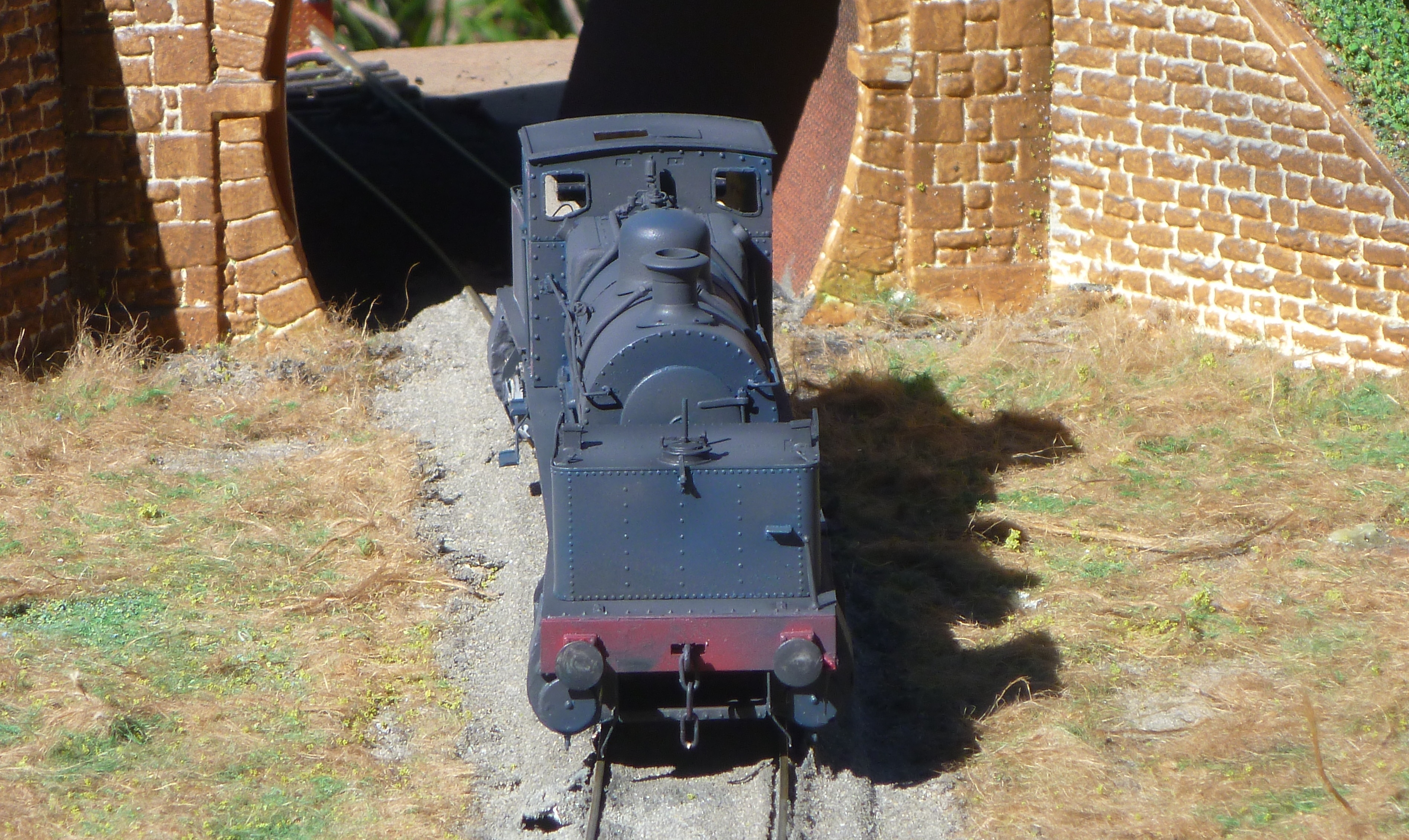
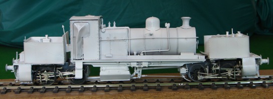
Well, the Garratt has progressed.  The construction is now finished, and I’ve put the primer on it.  It now looks a little like the prototype did when it emerged from the Beyer-Peacock work in Manchester and had its picture taken in “works grey”:

Also, I have decided that I should but no more model kits until I have built the one that I already have!  A radical approach I know, and judging by the article that I read, many other people have multitudes of kits lying arond the house waiting to be started.  The first benefit of this policy is that I have started to make the model of an LNWR gunpowder van.  I’m not sure that the LNWR ever actually had such wagons.  I have never been able to find a photograph of one like this kit is supposed to represent, and the instruction sheet which comes with the model is vague, inaccurate in parts, and covers several different models.  The attraction of the model is that the LNWR is reputed to have painted these gunpowder vans vermillion, so I could legitimately have a bright red wagon on my railway!  There is some doubt that this colour is true: the claim about the colour may be based upon a crude tinplate model made by Bassett-Lowke in the nineteen-fifties!  Nevertheless I shall build one.

Gunpowder van small


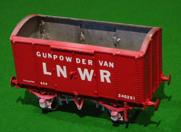
Here it is (as far as I have reached!):


For more entries, follow the links at the top or bottom of the pages, to go to “older posts”.

Video files from Melbourne

It has taken me some time to get these loaded, but here are a few video files of Richard Davidson’s circuit of track at his home outside Melbourne (a place called Melton).  This outdoor circuit is huge!  Richard tells me it is 60 yards around the loop, which is about a scale 2½ kilometers!

My industrial Garratt ran well, and so I want to celebrate this fact!

There are small files and larger ones, depending on how broad your broadband is

(is it a Gillard-government one, or an Abbott govt. one?).

WF outdoors 1 small  <-Small   Large -> WF outdoors 1

We loaded up the Garratt with 27 wagons: WF at RDs house

WF outdoors 2 small  <-Small   Large -> WF outdoors 2

I don’t think that the real one could have hauled this many!

WF outdoors 3 small <-Small   Large -> WF outdoors 3

In the last video it is possible to see Richard’s superb model of a North British 0-4-2 locomotive going in the opposite direction around his double loop of track.

Scale Seven in Melbourne

I spent a pleasant day in Melton, near Melbourne.  It was a day-trip (!) from Sydney to see fellow-ScaleSeven enthusiasts Richard Davidson and John Ritter.  The original idea had been to go to the VicG0G meeting, but somehow we never actually made it there.

Small WF outdoorsThis was mainly because Richard has a wonderful outdoor circuit, upon which we could run our trains.


S7 in Melbourne u - WF on the curved trackRichard has a large shed in the back garden, out of which the railway comes.  It then goes around a circuit of more than 50m of track and back into the other side of the same shed.


S7 in Melbourne s - WF from aboveAs you can see, I took my industrial Garratt (William Francis) down to Melbourne with me.  I’m pleased to say that WF ran very well during the day.


Small WF with 27 wagonsThe Garratt could haul a load of 27 wagons, which is the most it has ever pulled.  I do not have that many trucks myself, and in any case Richard’s wagons are better -built that my own, and offer less rolling-resistance, I suspect.

It drew 450mA current with or without a load of wagons, which is good even though it means there is probably too much friction in the locomotive running gear itself.  It ran so well that we left it running round and round for hours, which probably loosened up the running gear nicely.

Small Richards Caledonian engineRichard has some lovely locomotives as well as his magnificent collection of private owner wagons.

This one is Caledonian Railway 0-4-2 No 705, designed by George Brittain and built by Dubs in 1881.

As usual, click on pictures to enlarge.

In Richards words: it is scratchbuilt except for the gears (plastic, two start worm, 11:1 ratio ex motor car window winder).  The motor is ex computer, from Proops at $2.50, draws 12 mA light, 30 mA with gearbox and about 100-200 mA on a train. The wheels were fretted out of brass and insulated with a strip of thin perspex between the centre and the tyre.

Small Richards wooden-clad engine The second one is North British Railway 0-4-2 No 26, a mixed traffic engine built in 1845 by R & W Hawthorn of Leith. The original was fitted with a patent valve gear in which reversing and cut-off were controlled by separate levers. The valve was in two parts that slid over each other and the valve rod was hollow, with the cut-off rod inside it.

Again, Richards words: I built the engine with a crank axle but have got no further with the valve gear. The motor is a Mashima 1824 in the firebox, driving through a cut-away (27:1) North West Short Lines idler gearbox. The final drive gear is on the axle between the eccentrics and the idler gear is meshed with the worm in what is left of the gearbox. The mesh between the drive gear and the idler can be adjusted. The engine is also scratchbuilt except for the motor and gears. The livery is guesswork..

Small  WF at track level

8F progress

I’ve been working slowly on the “motion bracket” and the slidebars and crosshead assembly, toghether with some of the valve gear.

Here are some pictures of the progress so far:

Union link and radius bar - note the Y-shaped ends

Union link and radius bar – note the Y-shaped ends

Radius bar and expansion link.

Radius bar and expansion link.


Click to enlarge

Radius bar and expansion link in position, in the motion bracket.

Radius bar and expansion link in position, in the motion bracket.

Motion bracket, etc., in position on the frames.

Motion bracket, etc., in position on the frames.


A few notes of explanation.  The first shot shows the laminated rods, with bifurcated ends to allow joints with other pieces of valve gear: see the union link in the fourth picture (parallel to and below the cylinder slidebars); the expansion link is the curved piece through which the radius arm travels.  In most models the radius arm is left in a neutral position, thoguh the centre of the expansion link.  This is convenient, as the centre of the expansion link is the pivot about which it moves forward and back, but for the radius arm to be there is to have the model always in neutral gear.  So instead I am making my model in a forward gear, with the radius rod just below the central expansion link.  The radius arm will move forwards and back a very small amount as a consequence, but the construction should be able to be done reasonably easily (I think).

It’s possible to see this in the pictures if you look closely.  I had to create a pivot for the radius arm just below the central pivot of the expansion link.

Cylinders, slidebar, crosshead and some valve gear.

Cylinders, slidebar, crosshead and some valve gear.


The whole construction is made to come off the frames for ease of maintenance and building.

Not complete, of course.


Melbourne

I’ve been in Melbourne this week, at the World Congess of Cardiology.

Melbourne was cold and windy, as you might expect.  There are some mitigating features: trams, passenger trains hauled by locomotives (even if they are all Diesels), and I was once again struck by how much room and space there appears to be in near-Central Melbourne, compared with Sydney.

However there is also the casino.  This is truly horrible.  As well as the casino itself, there are at least four huge self-proclaimed luxury hotels attached to them, and they are all glitzy and to my mind deeply unattractive.  Even if you like “glitz and glam”, the concept of exploiting people’s complete lack of sense is morally dubious, to say the least.  No-one who has the slightest appreciation of the arithmetic of statistics can fail to understand that casinos or poker machines (aka One-armed Bandits) are a simple way for owners of casinos or clubs to make huge amounts of money from the gullible public.  The whole industry that has been allowed to grow up around this exploitation is appalling.  I understand that ideologically people should be allowed to make their own choices.  Nevertheless this transfer of wealth from the poor (who do most of the gambling) to the rich (who own the clubs and gambling houses), without even a decent amount of government taxation to reclaim some of the revenue to the state is definitely a case for government intervention.

The conference was good.