Actually, this is a tale which goes back to before the coulshed.com website existed, and then the website changed (at the beginning of 2012), so I am reconstructing the entries from before January 2012, in order.
 Click on any picture to enlarge it ! The start of making my model industrial 0-4-0+0-4-0 Beyer-Garratt in Scale Seven goes back to the middle of 2010. The kit was a decade in my cupboards waiting for me to summon the courage to tackle four sets of valve gear, never having constructed a model with valve gear before! The kit was a very basic one, designed for Finescale, “0-gauge”, and I decided to make it with near true scale-width frames, as well as the rest of S7 standards.
This meant that my first difficulty was to adapt the spacers for the driving-unit frames. The kit had “fold-up” frames, held also at the desired width by the buffer-beams and spacers on the inside end of the driving units.
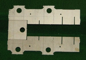 I was also planning to fit suspension to every axle, so slots to accept the suspension unit had to be cut in the frames themselves. I was also planning to fit suspension to every axle, so slots to accept the suspension unit had to be cut in the frames themselves.
This picture shows the flat fold-up frames with the scored markings to cut out the wide slots for the suspension units. The actual frames are seen above and below a horizontal plate, with the original axle holes about to be cut out.
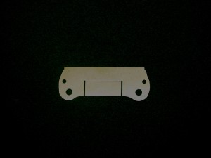
The buffer-beams and other spacers had to have new slots cut into them at the new width (29mm).
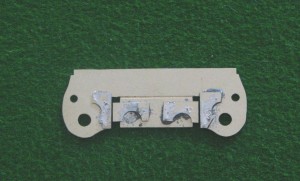
In the end the slots were just widened and scrap brass added to set the width of the frames, as shown.
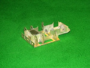 Frames upside down to show the slots for the suspension units
This was all very worrying, as it appeared to be a very destructive approach to kit-building! Fortunately all the calculations appeared to be working when I assembled the frames, as shown.
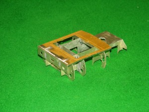 Front driving unit, from the front.
If you look carefully it is possible to see where the buffer-beam slots have been widened for the scale-width frames.
There then ensued a long struggle with the suspension units, the wheels, the “plunger” pick-ups and the coupling rods, just to get the units to move under their own power.
So many times I wondered if it was beyond me ….
This takes us up to the start of 2011, and the start of our website. The valve gear was yet to be done.
April 2011
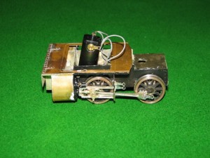 I should be able to put together some more of my model Garratt locomotive – an 040+040 industrial steam engine. Here’s a picture of the front end driving unit as so far built. The trouble building this to exact scale dimensions (Scale Seven) is a story in itself …. I should be able to put together some more of my model Garratt locomotive – an 040+040 industrial steam engine. Here’s a picture of the front end driving unit as so far built. The trouble building this to exact scale dimensions (Scale Seven) is a story in itself ….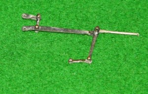 Looking after (ie staying in the house at the same time) as the two boys has some advantages: I took some time to construct some more of my Garratt. Looking after (ie staying in the house at the same time) as the two boys has some advantages: I took some time to construct some more of my Garratt.
Here’s my first ever construction of outside valve gear for a model steam engine – and it moves ! 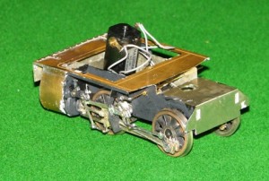 What makes it difficult is to make the joints all move. On the assembly shown below there are five joints made with brass pins soldered to etched brass valve gear “rods”. the pins are about 0.8mm diameter, 5mm long, and clearly the solder only has to fix the pin to one rod, and not the other. There are about ten joints like this for each set of valve gear – and there are four sets. What makes it difficult is to make the joints all move. On the assembly shown below there are five joints made with brass pins soldered to etched brass valve gear “rods”. the pins are about 0.8mm diameter, 5mm long, and clearly the solder only has to fix the pin to one rod, and not the other. There are about ten joints like this for each set of valve gear – and there are four sets.
I’m very proud to have successfully complete one!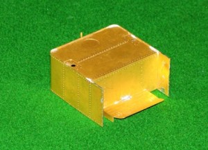 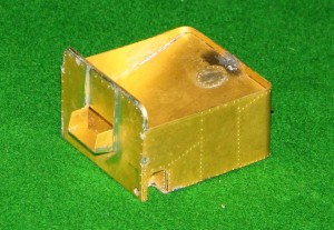 |
|
June 2011
As you can see, both sets of driving wheels are now complete with coupling and connecting rods, plus valve gear.
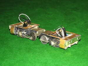
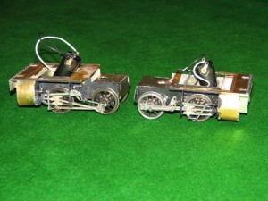
If only I could put moving pictures on the website, I could proudly demonstrate how it all moves and proceeds along the track!
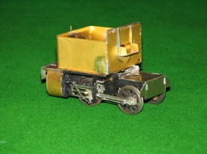
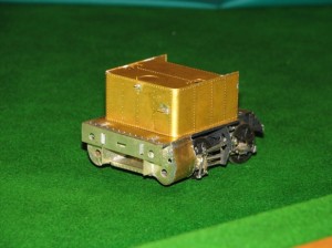 I have now fitted the bunker and the water tank onto the diving wheel assemblies of my model Garratt locomotive ….
October 2011
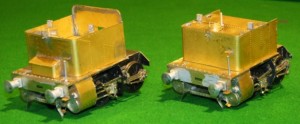 My model of the industrial Garratt “William Francis” is coming along quite well, now.
The first picture is of the two end units, with the rear one containing the coal bunker on the left and the front unit with a water tank on the right.
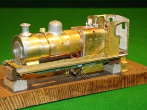 This is the central unit, with the boiler and cab.
It’s a very complicated model, and the kit (originally bought by me over a decade ago), is far from perfect or comprehensive. It’s really just a starting point for building a model of this industrial locomotive – adding detail is very much needed. However that is the part which I enjoy most, so that is certainly OK by me.
November 2011
My Garratt. It’s an 0-4-0+0-4-0 locomotive. The prototype ran in an industrial complex centred around a large coal mine in Warwickshire. It’s taken me a year to get this far, being quite a complex project. Here you are, though. Just three minor details to go (nameplates and a clack valve on the right hand side of the boiler).
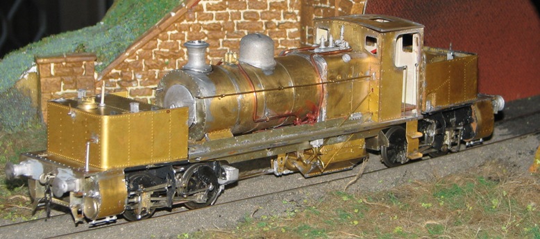
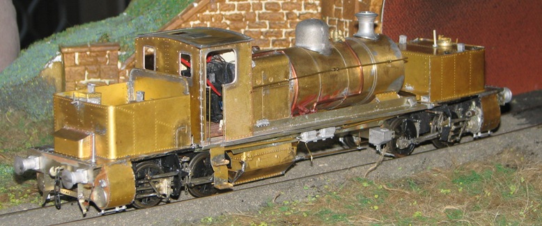
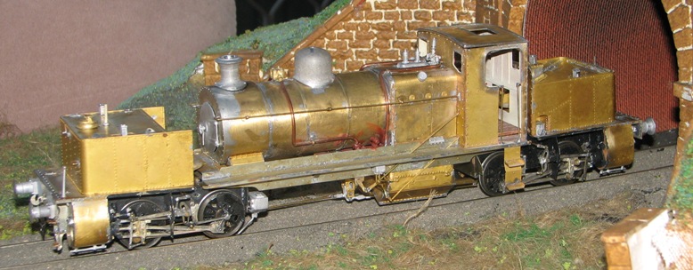
Then it will be on to the painting …
December 2011
So what have I been doing?
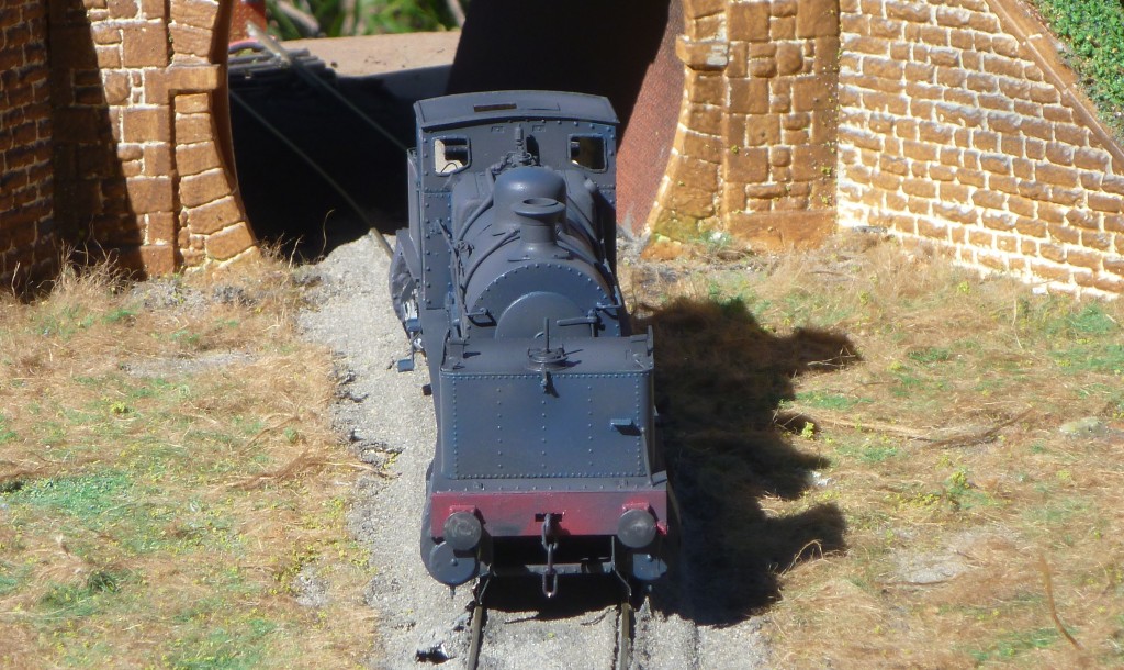
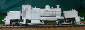 Well, the Garratt has progressed. The construction is now finished, and I’ve put the primer on it. It now looks a little like the prototype did when it emerged from the Beyer-Peacock work in Manchester and had its picture taken in “works grey”:
Also, I have decided that I should but no more model kits until I have built the one that I already have! A radical approach I know, and judging by the article that I read, many other people have multitudes of kits lying arond the house waiting to be started. The first benefit of this policy is that I have started to make the model of an LNWR gunpowder van. I’m not sure that the LNWR ever actually had such wagons. I have never been able to find a photograph of one like this kit is supposed to represent, and the instruction sheet which comes with the model is vague, inaccurate in parts, and covers several different models. The attraction of the model is that the LNWR is reputed to have painted these gunpowder vans vermillion, so I could legitimately have a bright red wagon on my railway! There is some doubt that this colour is true: the claim about the colour may be based upon a crude tinplate model made by Bassett-Lowke in the nineteen-fifties! Nevertheless I shall build one.
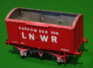
Here it is (as far as I have reached!):
For more entries, follow the links at the top or bottom of the pages, to go to “older posts”.


 I have now fitted the bunker and the water tank onto the diving wheel assemblies of my model Garratt locomotive ….
 My model of the industrial Garratt “William Francis” is coming along quite well, now.
 This is the central unit, with the boiler and cab.
 Well, the Garratt has progressed. The construction is now finished, and I’ve put the primer on it. It now looks a little like the prototype did when it emerged from the Beyer-Peacock work in Manchester and had its picture taken in “works grey”:


