 The Slaters Wheelset has arrived, and very nice it looks too.
They come with an innovation (to me) from Slaters: crankpins which can be screwed into a boss set on the crank.
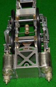
However  for wheels on an S7 version of the MOK kit, they create a problem, illustrated in this picture:
The crankpins are clearly too long in this case, and their rotation will be obstructed by the crosshead and slidebars.
Now I am familiar with this problem from when I widened the frames and cylinders, etc., for my S7 Industrial Garratt, and actually this doesn’t look quite as bad as that one did. However I will need to shorten the special crankpins made by Slaters (if you look closely I will need to cut them back to move a bit more that the threaded part of the pin), and then I will need somehow to reproduce a thread on the end of what remains.
With the old Slaters system it would have been easy, but here the crankins are completely different. The part threaded to go into the boss in the wheel is 10BA. The smooth part of the pin, to go inside the coupling rod and connecting rod bushes) is also 1.6mm O/D, but the retaining nut screw-thread is 12BA.
After seeking help from the experts/enthusiasts on the WesternThunder website, below is my first plan [I suspect that this is destined only to be the first plan]. The picture shows the frames with wheels in place. The front end is on the left. I am going to take advantage of the special construction of the S7 wheels, with the 10BA tapped holes for the crankpins.
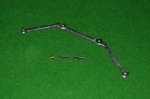
I am lucky in having my friend in Melbourne Richard Davidson who has done some work on his lathe for me. Below the frames in the picture are the special crankpins which Richard has made for me.
My illustration shows how I hope to arrange the crankpins. From the front: axles one and two have the special crankpins in place. Axle one the pin is part-way through the coupling rod. Axle two has the crankpin all the way home. Axle three and four have the Slaters crankpins. The ones for the connecting rod wheels are longer, and will take two brass bushes on top of each other, through the coupling and connecting rods. The final axle will have a standard Slaters crankpin and bush.
Clearances will remain extremely tight at the front end. I intend to try the front crankpin fitting direct to the wheel without a washer. The boss on the coupling rod is slightly thicker than the body of the rod itself, so as it goes round it should be clear of the central wheel boss. The second wheel will need a washer, though: the articulation of the coupling rod will catch on the central wheel boss otherwise. By the third axle, fortunately, the clearances should be less critical. So the flat portion of the Slaters crankpin, acting as a washer, will be less critical.
I hope that it all works …..


