I decided for some unknown reason to switch to the tender again. Perhaps because having succeeded with the brakes on the locomotive, I wanted to see if I could do them on the tender whilst the technique was still in my memory! So I measured the clearances, and found to my delight that no adjustment was really needed for ScaleSeven: the brake hangers could be soldered into the inner chassis frame and could be adjusted easily to be the correct clearance for the S7 wheels. Excellent. So I insulated the faces of the brake shoes as before, soldered the brake hangers and retried the running of the tender frames – it still works!
Next in the instructions is the water scoop lift gear. This proved to be a real challenge for me. There are times when I wish I was living in the UK (though not many ….) – the instruction sheet is really deficient in this section: “assembly is per diagrams and photos”; two unlabelled pictures and some difficult-to-decipher diagrams. It would have been much easier to be able to look at the real thing, but instead I had to look on the ‘net for drawings and pictures. It was almost too obscure even for the ubiquitous WWW: Google Images of “Stanier tender water scoop gear” produces almost no useful images! I eventually found some useful stuff – Some pictures of a model 3500 gallon LMS tender, and most useful were pictures of the Duchess and its tender in a Birmingham museum. I had to work out from their appearance what all the parts were for, and then how they go together. I hope I was right.
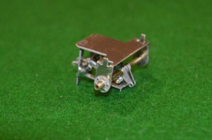
 The mechanism is mounted under a crossmember of the tender chassis, and appears to be a rod or axle (moved by a long control beam from the front of the tender) on which a number of cranks are mounted. The ones at the rear end (right of photo. here) are aimed to lift the water scoop itself.
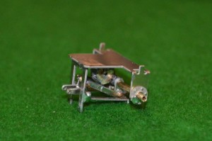
On the same axle are mounted levers which lower another device into the water troughs, the levers seen in the middle of the mech. and protruding to the left in the photo. below.

I’m not sure what this device did in real life – I guess that it was a deflector to channel more water from the edges of the water trough into the scoop?
There is also what I think must be a balance weight for the water scoop attached to the axle, seen in the middle of the mech. above (probably in the wrong position). I added to the thickness of the etched parts which represent this.
To make up the mechanism as seen above needed three parts to the frame (25 x 15 x 15mm), a piece of 1.6mm dia. rod, twelve tiny bits of etched nickel silver, half-a-dozen 1/32 brass pins and a HUGE amount of patience.
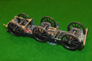
 Here it is in position:
Some of the brake gear is also seen, but no water scoop as yet.
If my deductions were wrong about where everything goes, I’m not sure that I really want to know ….
 Nick was playing today in Kingswood, so I took the opportunity to cycle down and watch him play. The “B Grade” competition may not be international standard, but it is still quite impressive to watch.


