[Updated four times]
While the Dyak 2-6-0 has its boiler removed for restoration and repair is clearly the best time to consider painting it. It has never been painted before, and as it isn’t a scale model of any particular, I could really paint it any colour I like (so long as it’s black …).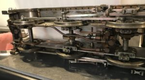
So I am going to have to take the wheels off, to paint the frames behind.
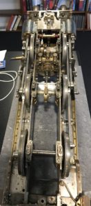
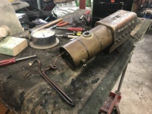
This is not simple. If you look at the driving wheels, I need to “drop” them as a unit (all six wheels) to make it a manageable task.If you look at the first picture, there are a lot of pipes in the way, and they have to be taken off first.
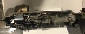
This picture shows from underneath what it looks like with the pipes removed.
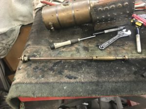
Trouble is, there are still two eccentric drives to be disconnected – for the axle water pump (for pumping water into the boiler as the wheels go around), and the mechanical lubricator.
Once the eccentrics are gone the wheels still aren’t free: the connecting rods and valve gear have to be disconnected first.

Then finally the wheels can be removed, complete with axle boxes.
All this, just to get black paint behind the wheels …
27th May. Having dismantled the engine as far as I dare, here is the result of painting on the “primer”. In the end I used a “rattle-can” (aerosol paint) as my airbrush simply wouldn’t handle the epoxy primer I had bought – even after thinning it with the special primer solvent.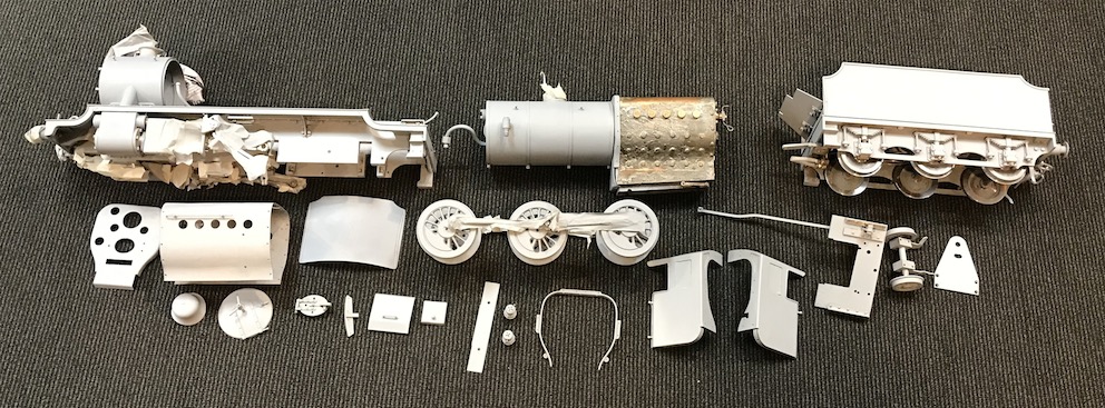
Much of the masking tape can be seen, trying to cover the moving parts and those which clearly shouldn’t be painted.
7th June. Painting it black was better – a rattle-can used at first, covering the majority, but the paint easily could be thinned (with the appropriate solvent), to fill in the areas not easily reached by the aerosol.
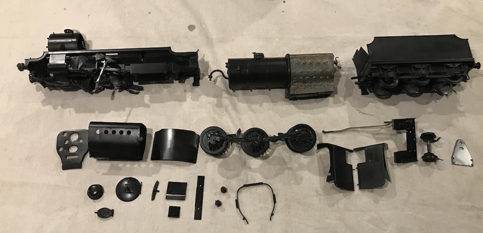 Now to the simple task of putting it back together …
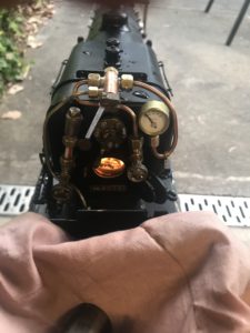
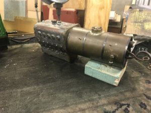
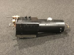 Now I have put the “Cladding” back on – the wrapping around the boiler firebox, and I have put some of the fittings back onto the boiler. Mostly the controls on the “back head” – the face of the firebox in the cab.
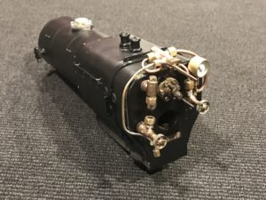 Here is a picture of the back head.
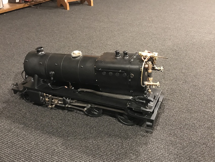
It’s now possible to get an idea (a very approximate one) of what the end result will be like:
This day was a great day …
On 28th June, the Dyak steamed for the first time, I believe, in about 50 years. It is a great tribute to Warwick Allison that this has proved possible. My original assessment was I think correct (that it had been very well made, but subsequently abandoned by whoever made it), but it was only with Warwick’s guidance that I could get it going!
So I took all the parts, now painted black, over to his house in Mount Riverview. First we had to reset the valve gear and make sure that it ran, on compressed air. Click on the link to view it at this stage: Dyak black no boiler
Next was to put the boiler back on, connect it up and make sure there were no leaks on compressed air. Yes, there were, but with Warwick’s help we found them all and fixed it up. It still didn’t have the cab on, but it looked much more like a locomotive now. We began the steam test: filled the boiler with warm water, put a fire in the firebox. This in itself was a good moment!
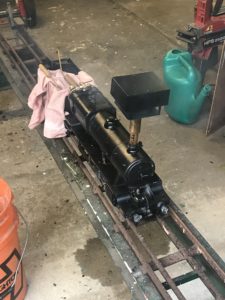 The fire initially was “kitty litter” soaked in kerosene, but after a while real coal could go in the firebox.
The orange cloth protected the tender, the gadget on the loco. chimney is a fan to “draw” the fire through the boiler.
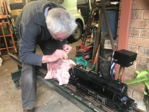 This is me supervising the steam-raising.
After what seems like ages, pressure was shown on the gauge, and I could hear the engine “blower” beginning to work.
Finally the great moment arrives: the engine wheels are propped up above the track, the regulator opened, and for what I guessed to be the first time in 50 years, the engine turns it wheels under the power of steam produced in its own boiler.
Click on the link to watch: Dyak first steaming 2.
So in the end I didn’t waste my money on 20kg of useless brass scrap ….
And as of 5th July
Engine running first time ever 5th July
By the way, I have decided that it is an “impressionist” model of a Stanier Mogul. It doesn’t have a taper boiler, the cab windows aren’t quite correct, and maybe the wheel sizes are wrong, but the tender looks right and the straight unstepped footplate makes it closer to a Stanier Mogul than any other locomotive that I have seen. There is the minor problem that the design for this model (the “Dyak”) and probably the manufacture of this particular example of it, pre-dates the first example of the real Stanier Mogul being made!

