
I’ve been working slowly on the “motion bracket” and the slidebars and crosshead assembly, toghether with some of the valve gear.
Here are some pictures of the progress so far:
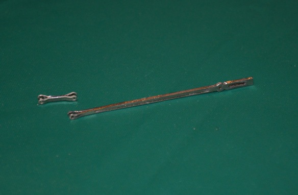
Union link and radius bar – note the Y-shaped ends
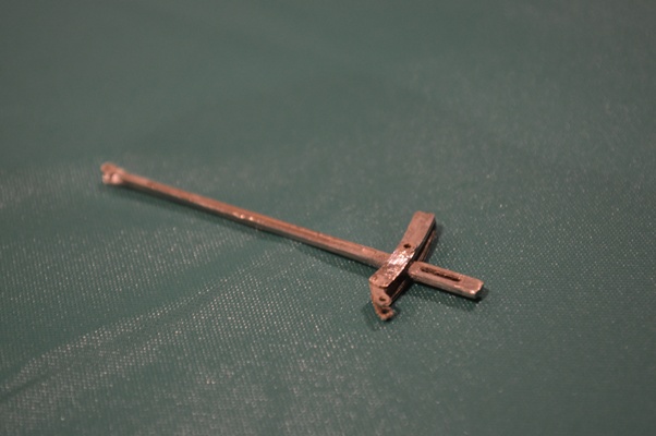
Radius bar and expansion link.
Click to enlarge
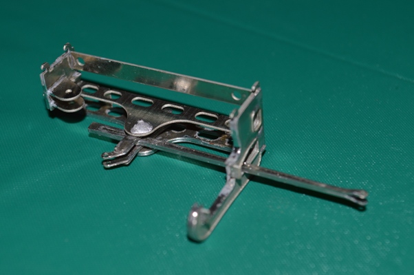
Radius bar and expansion link in position, in the motion bracket.
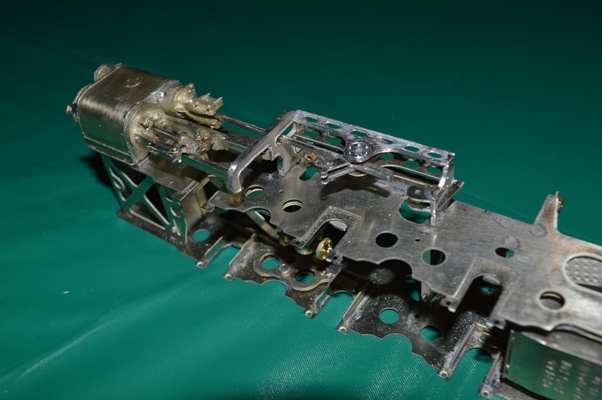
Motion bracket, etc., in position on the frames.
A few notes of explanation. The first shot shows the laminated rods, with bifurcated ends to allow joints with other pieces of valve gear: see the union link in the fourth picture (parallel to and below the cylinder slidebars); the expansion link is the curved piece through which the radius arm travels. In most models the radius arm is left in a neutral position, thoguh the centre of the expansion link. This is convenient, as the centre of the expansion link is the pivot about which it moves forward and back, but for the radius arm to be there is to have the model always in neutral gear. So instead I am making my model in a forward gear, with the radius rod just below the central expansion link. The radius arm will move forwards and back a very small amount as a consequence, but the construction should be able to be done reasonably easily (I think).
It’s possible to see this in the pictures if you look closely. I had to create a pivot for the radius arm just below the central pivot of the expansion link.
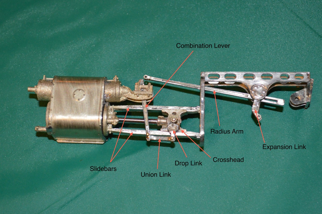
Cylinders, slidebar, crosshead and some valve gear.
The whole construction is made to come off the frames for ease of maintenance and building.
Not complete, of course.