
I may have made a mistake, which has exposed a difficulty/problem with the etches, not related to ScaleSeven however.
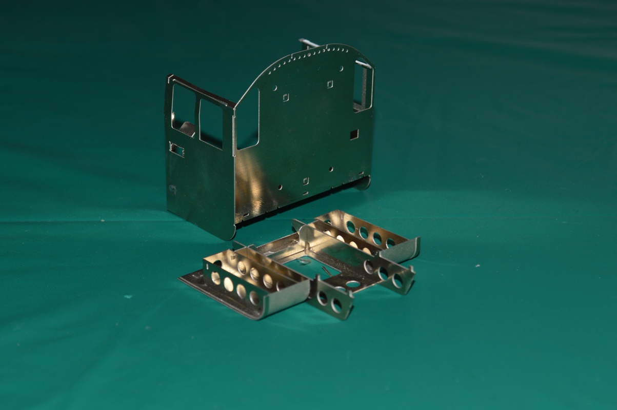
The first picture shows the overall basic construction of the cab: there is an undefloor part which I guess if faithful to the protoytpe, but is completely hidden one the parts are put together!
 On the underneath of the cab is part no 362, which is curved upward to make the curved plates leading up to the footplate.
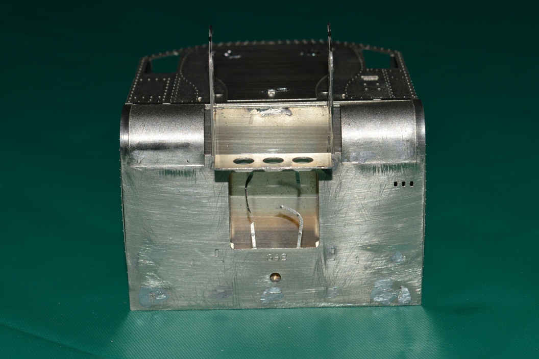
This shows that I may have put part number 362 on the wrong way up. I am guessing this because the three holes to take the damper levers have ended up on the wrong side. However putting it the other way up would mean that the fold for the panel at the front with three round gaps in it would be on the wrong side to bend it downwards – ie the bend would be away from the etched line. This is why I used it the way up which you can see in my pictures. Also the half-etched areas at the front on the curved plates I thought must be on the outside, because otherwise they would be completely hidden!
 So, if my analysis is correct, either the three holes for the damper levers are on the wrong side, or the etched line to fold the front plate is on the wrong side.
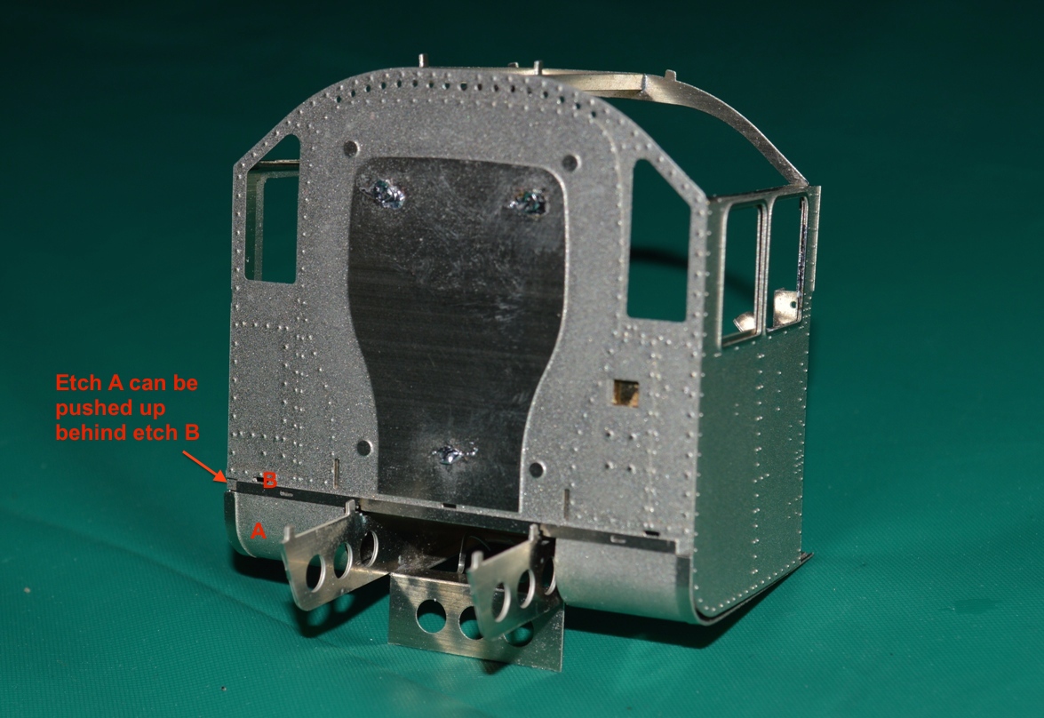
If you look at picture No.s 3 and 4, you can see that despite my care I have ended up with a gap between the cab-side etches and the curved part 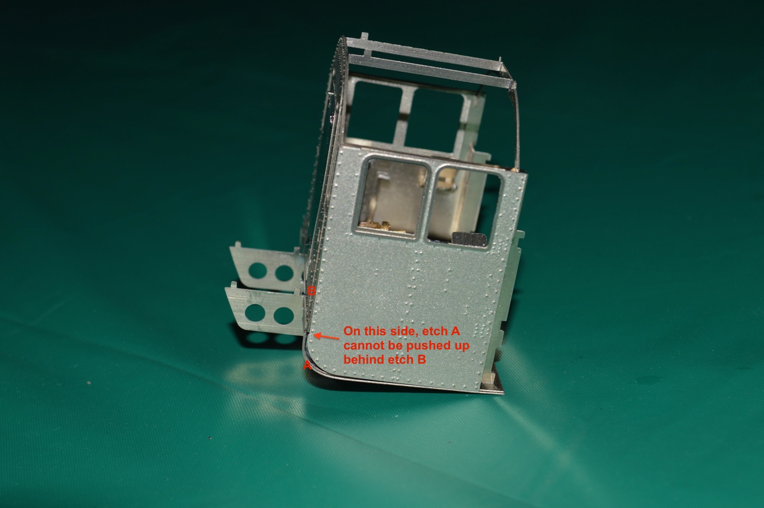 of part number 362.
On the right side this doesn’t matter, because if I push the curved part upwards, it neatly fits behind etch number 367 (this is the front of the cab, immediately behind the whitemetal firebox I think). This allows the shiny (unetched) strip at the side of the curved part on 362 to line up with the shiny strip along the lower edge of part number 367. Fine, it looks made to do just that. There will then be no gap along the bottom of the cab-side etch. The trouble is that on the left side, the curved part on 362 just abuts the thicker edge of part number 367 rather than going behind it, and leaves the curved part on 362 with a gap between that and the cab-side etch. This could be cured by removing a mm from the upper edge of part 362, but I’m reluctant to do that without knowing that it really needs to be done. Also with the assembly done so far, it will be awkward to do. However advice from the Scale Seven fraternity on the Western Thunder website suggests that I have put the base on upside-down and the removing a mm from the curved part is therefore exactly what I will have to do.
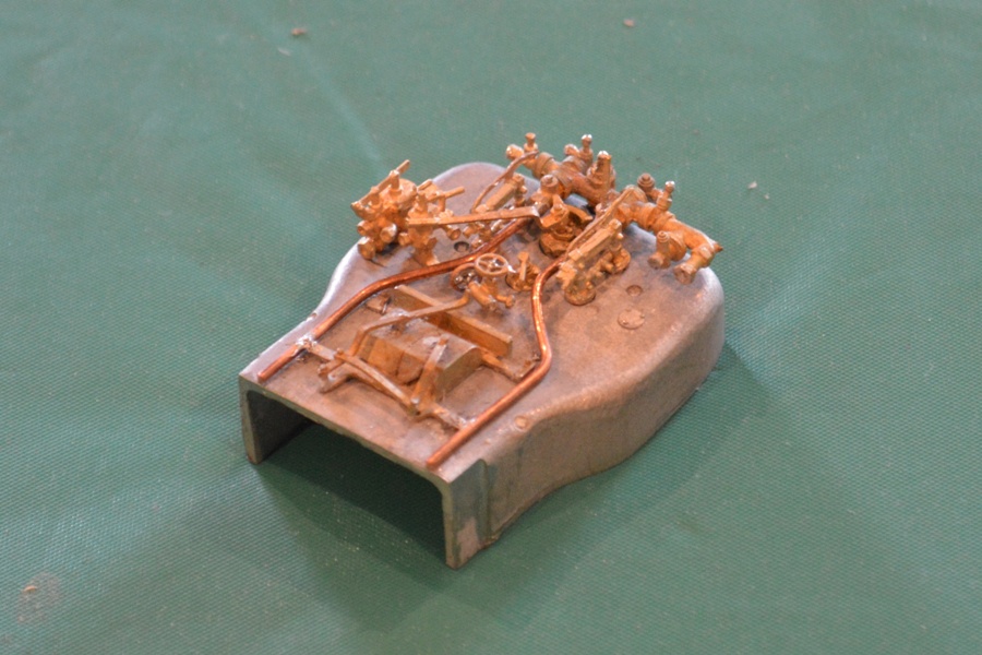
While I wait for the S7 wheels (for them to be sent to Aus., I want the whole lot at once, and I gather Slaters haven’t produced the pony truck wheels yet, although the others are ready), I have also been putting the details on the backhead.
It looks good so far, but it has been difficult to identify exactly where all the tiny lost-wax castings go.
I need to find views of the inside of an 8F cab, showing the backhead. The “Locomotive Profiles” books have two, but one is of an oil-burner, and the other one doesn’t seem to have the same components as provided in my kit. Mostly it is the same, but some parts are seemingly missing from the kit (the one described in the book as the “independent steam valve”), and doesn’t appear to be a casting either for the “blowdown valve” or one which goes where the steam sanding valve should fit, between the left water glass and the brake handle. There is a casting which can be seen in my picture placed in position, but if fixed there it will obstruct the regulator handle.
The pictures that I found via Google images didn’t help. Again I have turned to the WT website for help, and I am a little closer to answering my questions now. Later versions of the 8F don’t have the sand gun control valves in the centre of the backhead, and there are some other little details which I will have to change.
More pictures when it is done ….