Whilst waiting for parts needed for the main locomotive to come from the UK, I have started on the tender. The model kit is designed to have a “compensation” mechanism, which allows the rear two axles to move up and down independently. The front axle is fixed. This is shown in the picture below.
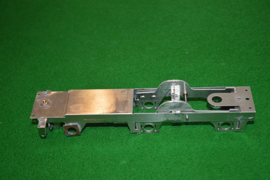 There are two inner plates which rock about the bar which can be seen crossing between the frames. On each plate there are two “loose links” which carry the axle bearings, and allow the axles to move at small angles in the plane perpendicular to the axis along the tender. The loose links are not shown in the picture.
These loose links I have had to modify anyway, to take double-sided circuit board, as part of the adaptation which will allow the wheels to be isolated from the frame, and allow electrical pick-up through a “split-axle” design. On the picture above, for the fixed axle at the front of the tender I have already soldered on the circuit board [it is not exactly straight, but this will be unseen and unimportant when the model is complete].
 This picture shows the loose links adapted with circuit board. The left-hand one has the double sided circuit-board soldered to the link. The loose links will have the side parts bent back at right-angles and slid through the slots seen on either side of the bearing holes in the rocker arms seen in the top picture.
The central loose link, seen with the c-b underneath, has had the loose link bored out with a countersink, which then allows the brass bearing to be inserted from the other side, remaining electrically isolated from the surface on the side closer to the camera, which will be in contact with the frame of the tender. This is seen on the right hand loose link.
 This way the wheels and axle are isolated from the frames although firmly fixed to the loose links, or main frames in the case of the fixed front axle, seen here.
Fortunately S7 wheels have a wider back-to-back measurement than normal Finescale 0-gauge wheels, allowing the insertion of the c-b.
It is all a complex way of allowing the rear two axles to rock independent of each other. I hope it works, with all the modification to take my split-axle pickup method!
Meanwhile the wheels and other items have arrived from England, and I have been able to put the coupling rods, driving wheels and hornblocks all together into the locomotive frames.
 I was not looking forward to this stage, actually, because of my previous experiences – two 0-4-0 locomotives and an 0-6-0, all of which I had problems with at this stage. In all three cases the coupled wheels had suffered from a lot of binding as the wheels went around, presumably because the coupling rods had slight different distances between the crankpins to the distances between the wheel centres. So the thought of all the adjustments necessary on an 0-8-0, and the enlargement of all the coupling rods crankpin holes was not pleasant.
This kit is in a different league.
I put it all together, turned it over, pushed the frames forward, and the wheels rotated perfectly. No binding. Even without any additional weight on the frames. MOK clearly have made the kit with perfect dimensional accuracy, although the correctly articulated coupling rods may help also. Whatever it is doesn’t really matter – it works!
Look carefully on the picture of the frames and you can see the 14BA nuts to be used to put the keeper plates on, to hold the hornblocks in place. 14BA is small, and MOK suggest 16BA!