Politics, the EU and Nationalism

I don’t often feel the need or have the inclination to indulge in political commentary, but  have read a couple of articles in the Economist over the past week which I want to share some thoughts from.

I have been watching what I regard as the tragedy of “Brexit” from afar.  It really affects me minimally, now, but for someone in my equivalent position in the UK it has nothing but “negatives” really.  However I can see why it has happened, and in my opinion those who think that the result can somehow be reversed are living in an alternative reality, because the fundamental reason for the “Leave” vote has not changed, and will not change in the short run.

In my opinion, the vote to leave is democracy at its best, even if I disagree with the verdict.

For years, possibly decades, the “elite” (whoever they are, and I would probably be counted as one, were I still living in England) have prospered, but the lower socio-economic classes have not.  In my opinion, the Thatcherite “trickle-down effect” has been demonstrated to be a false illusion.  Perhaps the economically-literate always knew it was such.  What has really occurred is that those in finance and the upper echelons of industry have become proportionately more wealthy, whilst those at the bottom of the social ladder have seen no benefits, or certainly have seen themselves relatively disadvantaged.  The riches earned by the “Bosses” have never been shared with the “Workers”.

On top of that certain politicians have seen career advantage to denigrate the European Union at every opportunity (Boris Johnson is the prime example of this).  So it can surely be seen as little surprise when the less-well-off in British society are firstly resentful of being told how well the country is doing (when their wages are stagnant even as the directors of companies take multi-million pound bonuses); and also see the EU as a source of many of their woes.

Brexit will, I believe, be disastrous for England (if Scotland achieves independence, then they may get some benefit from the process).  However those hurt dis-proportionally will be the well-off and middle-classes.  The poor of England may see little difference – if they were struggling before, and additional struggle from Brexit may go unnoticed.  They may obtain some satisfaction from the relative discomfiture of the elite classes, at least.

economist-brexit-chart

If you don’t think this can be true, click on this chart from the Economist and look at it.


It is from last weeks edition, and so reflects attitudes after all the negative publicity about Brexit that we have had recently.


My interpretation, in broad terms is this: the population still want all the advantages of EU membership, but without any of the obligations to countries poorer that the UK.  If the referendum were re-held tomorrow, the result would be substantially unchanged.  The EU is seen as responsible for the loss on manufacturing jobs and “blue collar” jobs in general, and even if finance-sector jobs have boomed, why should the population of Middlesborough/Liverpool/Glasgow care about that?

So unless Brexit can be shown to hurt the poor of England more than the rich, it is now inevitable.

The other article in the Economist was about globalisation, which is under significant attack by Trump and others.  the chart below is interesting for a number of reasons.

economist-stop-the-world-chart

Globalisation is not going to stop, when large countries like India and Indonesia want it to happen.  Also, protectionism (a la Trump) is not so easy in the era of the internet, Amazon, Alibaba, etc.

A final thought.  Look at the percentage of a population who believe that their country is the best in the world.  I knew that the USA would come top (a mass delusion that their society has much, indeed anything, to recommend it).  However I always thought that France would come high on this scale (we don’t meet many French immigrants – but perhaps it would be different in SE Asia, for instance).  However France is very lowly-rated.  So who is the next country after the USA to believe that their country is the best?  It is Australia.  The difference, of course, is that we are right.

Design for the new house in Glenbrook

Our dream house?  Not quite.  The council are interfering, apart from anything else.

house-design-1

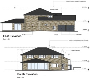
This is the appearance as we want it to be:


However the council are concerned about the two-level garage part of the building, and so that may have to be reduced in height.  I hope not, as that might mean we will lose the storage room above the garage – which is the only potential junk room, not immediately visible to Sue, in the house.  All homes need a room to put things in “which might be useful” in the future.

These are the square-on aspects:

house-design-4house-design-5


The block of land was attractive when we bought it because it is also flat, and is about 50m by 20m, so there is plenty of room.  The house will be as environmentally-friendly as we can make it.  Double-glazed, sealed to make it thermally efficient, rainwater-collecting into tanks and solar panels on the roof (ones can now be obtained to look just like roof tiles).  It will be made in local sandstone, and we will try to use materials from as local a source as we can.

One of the good parts of having a flat block of land could be the garden railway.  Would it be Gauge 1 (45mm track width) or Gauge 3 (63mm track width)?

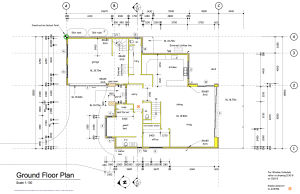
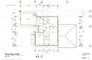
Click on the images to enlarge (if you are interested ….), these are the ground and first-floor plans:

screen-shot-2016-12-04-at-12-53-26-pmhouse-design-3Ground floor: large living area, garage swung around so as not to dominate the facade of the house, downstairs bedroom, large deck outside a large sliding glass door.

Front entrance with view up to the second level.


Upper floor: three bedrooms.  Room above the garage for suitcases, tools, etc.


Roof over the garage with “Velux” windows over the train hobby storage room.


Stanier 8F in ScaleSeven – Part 26: in Primer

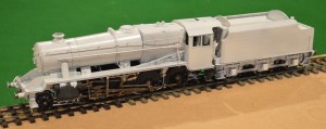
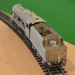
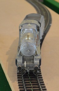
Onto the painting!  An exciting moment.  I have put the metal primer on already.

small-primer-01

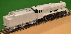
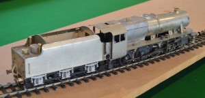
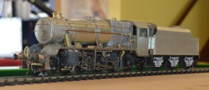
Here are a couple of pictures of the loco. and tender together.


small-primer-04The chassis and wheels have been partially painted already.

There are some modellers who assemble the entire kit before even starting to paint it, but this means that you are forced to take apart some of the construction in order to paint awkward places like behind the wheels, and so I have chosen to do a limited amount of painting as I go through.

small-primer-02small-primer-03For undercoat I use some stuff found in Australia made by a car-paint firm call Hi-Tech, who make some really good primer called (surprise) “All-Surface Primer”. I’m sure there would be equivalents made elsewhere.  Advantages are that it will stick to anything (I have to use a Stanley knife blade as a scraper to get it off the polished granite samples that we have from when we chose our benchtop in the kitchen) and that it is really thin and so easily applied by an airbrush.

I am going to have to slacken off the coupling between the tender and the locomotive, because at present there is too little movement side-to-side to allow the loco. to go around the somewhat tighter-than-realistic curves on my layout.


Property development.

Do you like this house?

47-park-street-1About five years ago we bought this house, In Glenbrook (a village near to where we live now).

It had six bedrooms, a large kitchen, a tandem double garage and a swimming pool.  However its main virtues were the fact that it stood on a 1000 square metre flat block of land, 50m from Glenbrook shops and restaurants, across from a public park and only 2-300m from the train station.

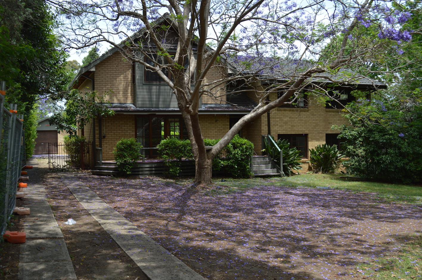
I trust you noticed the tense of those last few verbs, and I hope you didn’t like the house, because this is what it looks like today:47-park-street-2
This is the start of a year-long process of rebuilding the house to our own liking.  It will be a four-bedroom, sandstone house with solar panels built into the roof tiles, water-conservation plans, double-glazing throughout, thermal efficiency, top-class insulation all round.  In many ways I accept that it is an incredible indulgence, but it should set us up well for our declining-mobility years!

I will provide instalments here as we go through the process.

Stanier 8F in ScaleSeven – Part 25: build finished, prior to painting.

small-build-complete-01

I think most of the details are done, and I have put it all together.

img_0305

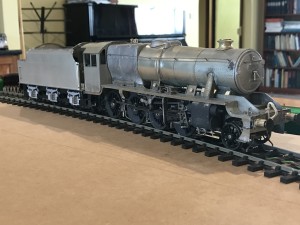
These are some pictures taken on my new iPhone:


img_0304


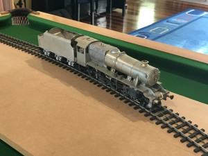
And others from the normal camera:

small-build-complete-02


small-build-complete-05 small-build-complete-06 small-build-complete-03


So for the first time, it can run as a complete locomotive:

It doesn’t run smoothly because of electrical “shorting” between the front steps and the pony truck wheels at the from, when traversing the tight curves on my test track.

.

Stanier 8F in ScaleSeven – part 24: the “fall plate”

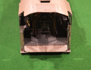
The “fall plate is (I think!) the footplate between the locomotive and the tender.  This clearly has to move up and down, and even on a model some movement will be necessary.

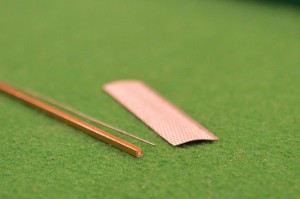
fall-plate-fitting-01In the MOK kit the fall plate is an etched rectangular plate with the grip etched onto one side.  There are cutouts for the hinges, which were assembled onto the cab sub-assembly earlier.

There were no instructions as to how to fit this part.  There is a second matching rectangle with no surface grip.  Both have a half-etched edge, but it is far from clear how this could be used.  I didn’t use the second plain etch.  I curved the etched plate (as seen above) and decided to hinge the plate by attaching a tube to the underside and using 0.5mm wire through the hinge-brackets.  I couldn’t find any small tubing in my scrap-box, but a U-shaped piece of brass channel made a better substitute.

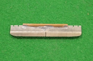
fall-plate-fitting-03So I soldered a 35mm length of the channel to the edge of the fall plate, and then filed the rear edges of the plate to resemble the fall plate seen on p76 of the “Locomotive Profiles” book of the Stanier 8F (IMO an essential acquisition if you are going to make an accurate model).


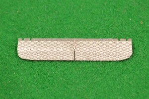
fall-plate-fitting-02The picture in LP shows two fall plates, not one, so accurately to represent this appearance, once I had soldered the brass channel in place, I used a piercing saw to separate the two halves (well, actually not quite separate them, but create that appearance).


fall-plate-fitting-04


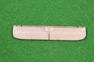
I then added the “hinges” by sticking paper squares onto the fall plate with cyano-acrylate glue.


fall-plate-fitting-05


I then threaded the 0.5mm wire through one hinge on the rear of the cab assembly, then through the channel on the fall plate, then through the other hinge.  Easier said than done!


fall-plate-fitting-06


I then cut the wire just the right length to fit between the cab side etches.


fall-plate-fitting-07This gave the right appearance (I hope) with some flexibility to flap up and down.


Stanier 8F in ScaleSeven – part 23: sanding gear

We are getting to the final stages of construction now.

The details is being added to the body and the frames.  I have added much of the detail, provided by the kit manufacturer, to the body itself.  This is about adding the sanding gear.  On the prototype, this is the equipment aimed to spray sand in-between the rails and the driving wheels to improve adhesion in slippery conditions.  There are three sandboxes, with tubes going out of them down to just in front of the leading driving wheel, and both in front of and behind the third driving wheel.

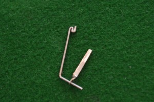
In this kit there are brass castings of all three sandboxes, even though two of them are inside the frames.  The outside one goes to behind the third driving wheel and has an additional mechanism (I don”t know what function it has) beneath the sandbox itself.  The sand-delivery tubes are represented by 0.8mm nickel-silver wire bent to shape, and I made support brackets from thin strips of scrap n/s with 0.8mm holes bored in the ends, twisted and bent to shape.

small-sanding-gear-01


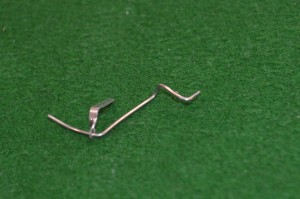
Here is the one for the outside sandbox, with a folded-up section of wire to represent the additional mechanism.


small-sanding-gear-03


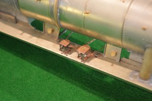
Once bent up and soldered onto the frames, this is the (unpainted) appearance.


small-sanding-gear-02The central sandbox, supplying sand to the front of the third driving wheel, was even more of a challenge, and in the end I made wire with multiple bends in it, allowing one end to be anchored to the sandbox, with the other supported by a bracket in position near the driving wheel.

small-sanding-gear-04

This shows the course inside the frames of the central sandbox “tubing”.


This side-on view shows all the three sanding jets in place.  Of the sandboxes, only the rear one is outside the frames and visible.

small-sanding-gear-05


Cricket, and psychology

I had an excellent day playing cricket yesterday.  Actually, it does’t sound much, 11 runs, but it was very good, for me.

I opened the innings for our side – facing the first ball – with a target of about 112 I think.  We had an opening partnership of 43, off about the first 15 overs (out of 35).  We weathered the storm of their opening bowlers, and not only could I defend, but this innings for the first time I managed the transition from pure defence to starting to attack.  I managed to pick the bad balls and hit them, whilst picking the danger balls and defending.  A few really good shots gave me confidence.  A nice square cut for two (I was disappointed it didn’t reach the boundary, it was hit cleanly but along the ground) and my first four.  Actually I have this vague recollection of accidentally edging a four a couple of seasons ago, but that doesn’t count.

Nick was there to see me bat, and says it looked good.  Even Dave Hadden, who is a very harsh critic, said that I played some good shots.  When I was out, it was to a pulled shot which went up in the air and was caught, but by that stage we had laid the foundations for what proved to be a successful run chase, and I either needed to accelerate the scoring or get out of the way of someone who could.

So I was pleased.  Ridiculously pleased.  Even several of the opposition (a really good bunch of blokes from Glenmore Park, many from “the subcontinent”) said I had batted well.

So what had changed?  Actually in some respects I think it is that I hadn’t been practicing so hard, and so in a bizarre sort of way didn’t feel quite the same pressure to show results!

I can hardly walk today, though, for my aching muscles.

Stanier 8F in ScaleSeven – part 22: Mechanical lubricators and their pipes

I’m beginning to wonder just how obsessive/nerdy I can get.

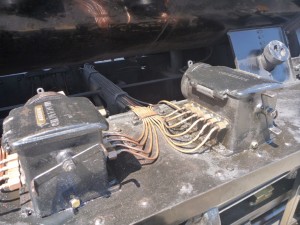
On my recent visit to England (see John’s ‘blog), we travelled behind one of my beloved Stanier 8Fs on the Scarborough Spa Express.  I took pictures of the engine, and noticed many details that would be useful for my model.

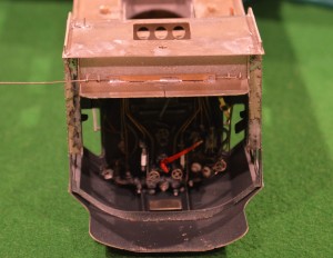
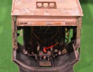
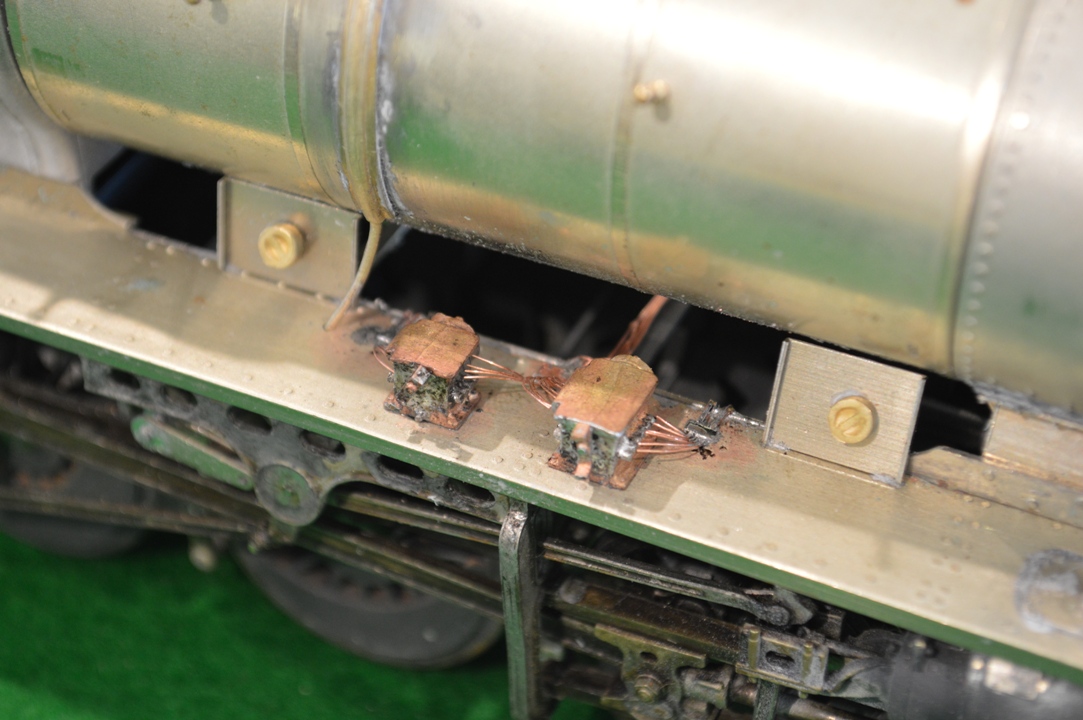
Small mechanical lubricatorsAmongst these were the mechanical lubricators and their pipes.  They were all cleaned and nicely polished, and so were a quite prominent feature on the footplate of the locomotive.  In working life they would probably have been grimy and not noticeable, I suppose, but now I had seen them, I felt I had to model them accurately.


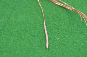
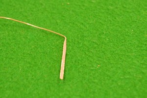
The MOK kit comes with the two lubricators, but not with the pipes which go from them.  So I had to somehow make the pipes from scratch.  Stripping some mains cable I found multi-strand copper wire with which to make the pipes.  Each strand was about 0.2mm thick, so approx. scale for a pipe 8-9mm across, which seemed about right.  However, how to make them into the beautiful fan of pipework was not obvious, to say the least.  I tried soldering the wires to the lubricator castings, but apart from clogging everything with solder, well you can imagine how successful that was.  I then tried soldering the wire strands into ribbons six wires across, intending to use lower-melt solder to attach them to the lubricators.  However I couldn’t solder the wires together over a short enough length then to make the elegant curved sections onto the castings.  Lots of burnt fingers and strained eyes.
Small MtML 07

This is how I eventually did get something approximating to the desired appearance.

Click to enlarge.


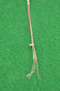
First I found some thicker copper mains cable, and flattened a section out with a hammer, evening its edges up with a file.

Small MtML 01Small MtML 02


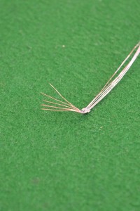
Next I cut a small section of this cooper strip and folded it over the necessary number of strands of 0.2mm wire and hammered the folded copper strip together to hold the wire, applying a tiny amount of solder to keep it all fixed.  Then I could bend the curves into the ends of 0.2mm wire and separate them to go up to the lubricators.

Small MtML 03.Small MtML 04


Small MtML 05The one in between the two lubricators had to take ten wires/pipes, divided to go different directions, of course!

The fixing strips were then used to attach the pipes to the footplate, in a position so that the curved pipes are coming from the sides of the lubricators.

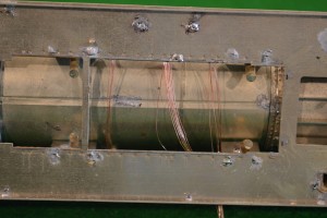
Small MtML 09The other end of the multiple-wire constructions help to hold the curved ends in place when soldering, and can then be bent into shape to represent the lubricator lines as then do down or across the chassis – a few travel across to the other side over a chassis cross-member, and are visible from above.


Small MtML 08Was it worth all the trouble?  I don’t really know, but it is satisfying to have succeeded, so if the painting eventually makes it invisible, i may just have to be content with that.