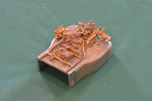
Scale Seven Model Stanier 8F Locomotive Part 8 – the wheels

Small Slaters S7 8F wheelsThe Slaters Wheelset has arrived, and very nice it looks too.


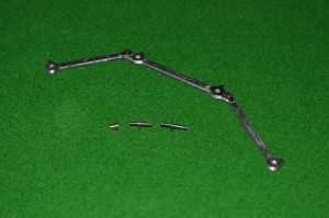
Coupling rods (articulated as shown), crankpins and crankpin bush

Coupling rods (articulated as shown), crankpins and crankpin bush

They come with an innovation (to me) from Slaters: crankpins which can be screwed into a boss set on the crank.


However Small Crosshead and S7 8F wheelsfor wheels on an S7 version of the MOK kit, they create a problem, illustrated in this picture:
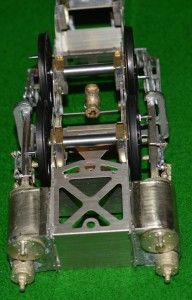
The crankpins are clearly too long in this case, and their rotation will be obstructed by the crosshead and slidebars.
Now I am familiar with this problem from when I widened the frames and cylinders, etc., for my S7 Industrial Garratt, and actually this doesn’t look quite as bad as that one did. However I will need to shorten the special crankpins made by Slaters (if you look closely I will need to cut them back to move a bit more that the threaded part of the pin), and then I will need somehow to reproduce a thread on the end of what remains.
With the old Slaters system it would have been easy, but here the crankins are completely different.  The part threaded to go into the boss in the wheel is 10BA.  The smooth part of the pin, to go inside the coupling rod and connecting rod bushes) is also 1.6mm O/D, but the retaining nut screw-thread is 12BA.

After seeking help from the experts/enthusiasts on the WesternThunder website, below is my first plan [I suspect that this is destined only to be the first plan]. The picture shows the frames with wheels in place. The front end is on the left. I am going to take advantage of the special construction of the S7 wheels, with the 10BA tapped holes for the crankpins.

Coupling rods and crankpins 02

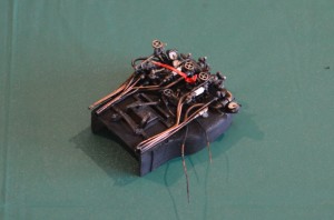
I am lucky in having my friend in Melbourne Richard Davidson who has done some work on his lathe for me. Below the frames in the picture are the special crankpins which Richard has made for me.
My illustration shows how I hope to arrange the crankpins. From the front: axles one and two have the special crankpins in place. Axle one the pin is part-way through the coupling rod. Axle two has the crankpin all the way home. Axle three and four have the Slaters crankpins. The ones for the connecting rod wheels are longer, and will take two brass bushes on top of each other, through the coupling and connecting rods. The final axle will have a standard Slaters crankpin and bush.
Clearances will remain extremely tight at the front end. I intend to try the front crankpin fitting direct to the wheel without a washer. The boss on the coupling rod is slightly thicker than the body of the rod itself, so as it goes round it should be clear of the central wheel boss. The second wheel will need a washer, though: the articulation of the coupling rod will catch on the central wheel boss otherwise. By the third axle, fortunately, the clearances should be less critical. So the flat portion of the Slaters crankpin, acting as a washer, will be less critical.

I hope that it all works …..

Norfolk Island

We have just returned from Norfolk Island.

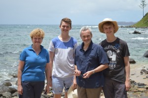
We spent ten days there.  It is an unusual place, Norfolk Island familybeing part of Australia and NSW, but being an “overseas territory” and so not governed by many of the laws of NSW: it is duty free, there is no income tax, and other anomalies.  On the other hand, the currency is Australian Dollars, and the population are Australian citizens.


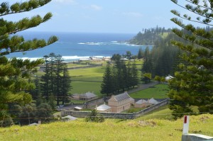
Norfolk Island convict buildings

There is a historical interest on the island, in that it was a penal colony, and after that use ceased, it was the final destination for the descendants of the sailors involved in the mutiny on HMS Bounty.


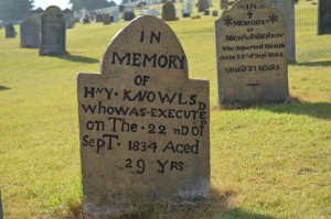
Norfolk Island convict gravesWe spent some time looking around the old buildings, and even the graveyard has some interest, with the headstones showing signs of beingmade by people who had difficulty spelling and certainly amateurs at spacing out he letters on the stones!


The best parts of the holiday, though, were such things as going on a day’s course on how to prepare restaurant-standard meals.

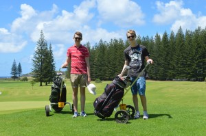
Norfolk Island golfAndrew and Nick had a couple of golf lessons and played their first couple of rounds of golf.


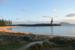
Norfolk Island Emily Bay

We also spent some hours swimming in Emily Bay, a beautiful place to swim: and omega-shaped bay, with coral reefs across the entrance.  So no surf, gentle waves, and excellent snorkling to be done.  My (David’s) swimming improved greatly.  I swum further than I have ever done before: more tha 250m!  It may not be very far, but to me this is a triumph.

Christmas Day 2014

How life changes.  The boys, being bigger than us, now no longer expect us to put out presents from Father Christmas, and Andrew couldn’t believe that I put out carrots and a bowl of milk for Father Christmas’s reindeer last year ….

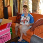
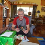
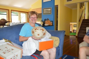
Presents can now arrive (wrapped) from on-line purchases arranged from Australian suppliers by people in England.  So, John and Mark, Thank You from the Australian Coulsheds, and here are pictures to show you what your presents looked like!

Small Christmas Day 01First the bowl from Peter’s of Kensington arrived wrapped like this:


Then these were the books and other presents:

Small Christmas Day 03Small Christmas Day 02Small Christmas Day 04


Small Christmas Day 05This is what the bowl looked like – excellent choice!


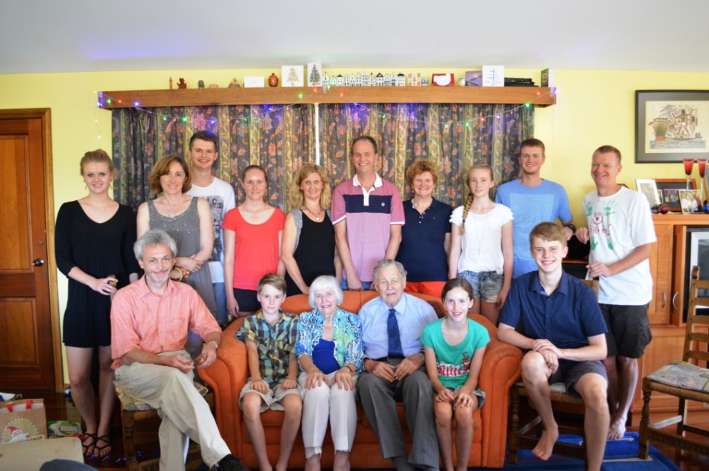
We had a large faily gathering here in Mount Riverview.  The Nicklins were particularly keen for us all to be together, and Nicola and Hamish are going far away this coming year, so this may be the last time we all gather together.

Small Christmas Day 07

L to R: Nicola Wallace, David Coulshed, Debbie Nicklin, Nick C, Claire N, Riley N, Robyn W, Margery N, Tony N, Malcolm N, Sue C, Anneka N, Lucy N, Hamish W, Andrew C and Richard W.


Cricket

We lost our cricket match this weekend from an almost-impossible-to-lose position ….

This is Ninth Grade, though, and all sorts of funny things occur.  It’s all against a background of all Australian cricketers being caught up in mourning the untimely death of Phillip Hughes.  A freak accident, and much has been written about it.  Personally, I think the best article was this one:

http://www.theguardian.com/sport/blog/2014/nov/27/cricket-naked-aggression-calm-down-phillip-hughes-death

Small Minutes silence for Philip Hughes


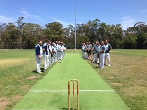
We played StMarys Leagues CC this Saturday, and the two teams met in the middle for a minute’s silence as tribute.


My team then went on to fail to defend our total (from the previous week) of 172.  SMLCC only had ten men, and we had them down to the last wicket at 8/108.  However a tremendous last-wicket stand allowed them to snatch victory from the jaws of defeat.  It was achieved by just sensible batting, taking no chances, and just inching towrds victory.  I was also sad that our captain didn’t give me a chance to bowl: we had medium/fast bowlers from both ends for all of the afternoon, and giving my loopy leg-breaks a chance might just have upset the batsmen’s concentration and reaped the one wicket reward that we needed.

I suspect that the problem was that a certain character from our club turned up to watch and said that it was clearly sensible to bowl a slow bowler, even one of doubtful ability.  No chance, after that statement ….

Model 8F Part 7: Cab re-construction

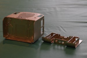
Following on from part 6, I found out from MOK (Dave Sharp) that I had definitely put the base of the cab on upside down.  This has all sorts of minor but annoying effects.  One was the fact that the formers inside the base of the cab had been made to accommodate the etched plates which were meant to go inside the curved sections (making them invisible – they are there only to make curving these areas easier).  So the formers made the curved plates have a larger diameter of curve – hence leaving a gap at the outer end: exactly where I had found one.

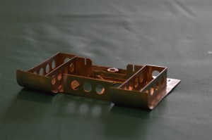
Small Cab reconstruction 002After much debate inside myself, I decided that I would never be happy if I did not do the job properly, so I pulled all the cab base apart using a 75 Watt soldering iron.  Once back to the component parts I tried to clean all the solder off the nickel-silver, then I flattened the bottom plate completely (apart from the front plate [see below]) first with my fingers, then with Small Cab reconstruction 003a tap hammer on a piece of flat granite.  The front plate (with three holes) is now bent upwards as it should be.

I then reformed the curves, fitted the formers back (now easier because the former correctly fitted onto the curved sections.  At the point shown in the picture, my soldering iron stopped working.  So I have sent off for a replacement.

Whilst I wait for a new 25 Watt soldering iron, here is a picture of the completed boiler backhead.

Small Backhead painted 1I am quite pleased with it.  Basically I followed what fittings I could see on photo.s of preserved and other engines, and then upt as many pipes as I could on the brass castings, to be realistic.  I “painted” it using metal blackener, scraped some off the copper pipes and painted the dials and water gauges by hand.  A thin covering of matt varnish to complete the work.

Thought for the day

This is a picture oNicks Med School Year Groupf about half of the students in the First Year at University Of Western Sydney Medical School.

In this picture there are about 16 European-background Australians, out of about 70 students.  Only about half the these come straight from school.

“Whities” just don’t work hard enough ….

Model 8F construction Part 6

I may have made a mistake, which has exposed a difficulty/problem with the etches, not related to ScaleSeven however.
Cab underfloor
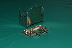
The first picture shows the overall basic construction of the cab: there is an undefloor part which I guess if faithful to the protoytpe, but is completely hidden one the parts are put together!

Small Cab pictures 01 On the underneath of the cab is part no 362, which is curved upward to make the curved plates leading up to the footplate.

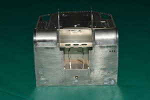
This shows that I may have put part number 362 on the wrong way up. I am guessing this because the three holes to take the damper levers have ended up on the wrong side. However putting it the other way up would mean that the fold for the panel at the front with three round gaps in it would be on the wrong side to bend it downwards – ie the bend would be away from the etched line. This is why I used it the way up which you can see in my pictures. Also the half-etched areas at the front on the curved plates I thought must be on the outside, because otherwise they would be completely hidden!
Small Cab pictures 02 So, if my analysis is correct, either the three holes for the damper levers are on the wrong side, or the etched line to fold the front plate is on the wrong side.
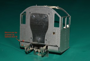
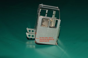
If you look at picture No.s 3 and 4, you can see that despite my care I have ended up with a gap between the cab-side etches and the curved part Small Cab pictures 03of part number 362.

On the right side this doesn’t matter, because if I push the curved part upwards, it neatly fits behind etch number 367 (this is the front of the cab, immediately behind the whitemetal firebox I think). This allows the shiny (unetched) strip at the side of the curved part on 362 to line up with the shiny strip along the lower edge of part number 367. Fine, it looks made to do just that. There will then be no gap along the bottom of the cab-side etch. The trouble is that on the left side, the curved part on 362 just abuts the thicker edge of part number 367 rather than going behind it, and leaves the curved part on 362 with a gap between that and the cab-side etch. This could be cured by removing a mm from the upper edge of part 362, but I’m reluctant to do that without knowing that it really needs to be done. Also with the assembly done so far, it will be awkward to do.  However advice from the Scale Seven fraternity on the Western Thunder website suggests that I have put the base on upside-down and the removing a mm from the curved part is therefore exactly what I will have to do.

Small Backhead 01

While I wait for the S7 wheels (for them to be sent to Aus., I want the whole lot at once, and I gather Slaters haven’t produced the pony truck wheels yet, although the others are ready), I have also been putting the details on the backhead.

It looks good so far, but it has been difficult to identify exactly where all the tiny lost-wax castings go.

I need to find views of the inside of an 8F cab, showing the backhead.  The “Locomotive Profiles” books have two, but one is of an oil-burner, and the other one doesn’t seem to have the same components as provided in my kit. Mostly it is the same, but some parts are seemingly missing from the kit (the one described in the book as the “independent steam valve”), and doesn’t appear to be a casting either for the “blowdown valve” or one which goes where the steam sanding valve should fit, between the left water glass and the brake handle. There is a casting which can be seen in my picture placed in position, but if fixed there it will obstruct the regulator handle.

The pictures that I found via Google images didn’t help.  Again I have turned to the WT website for help, and I am a little closer to answering my questions now.  Later versions of the 8F don’t have the sand gun control valves in the centre of the backhead, and there are some other little details which I will have to change.

More pictures when it is done ….