Stanier 8F in S7 part 13: rolling the smokebox.

Onto the best bit (for me) – building the loco body (I’ve never built a tender before, but that should be good as well).  Actually going on to building the superstructure may be good mainly because I am stressed out about making the wheels go around without binding, so when the chassis is complete I breathe a sigh of relief and relax ….
Early on in the build comes the boiler and smokebox construction.  Now the instructions say that both are “pre-rolled”, but only my boiler was treated this way.  The smokebox was a pair of flat etches (there is a beautiful thin overlay with all the detail on it).  So this is the dilemma: I have never tried to roll a piece of flat metal into a cylinder, so is this the right time to start?  Do I risk ruining my lovely MOK kit, or do I beg someone to roll it for me?  If so, who?  Or do I buy a special rolling tool (about $90 here in Aus., which I may never use again)?
The instructions talk about rolling the (much thinner) overlay using a metal bar and some cloth so press it down onto.  So the main structural part of the smokebox should surely be bend-able in the same way ….
So I try rolling the (0.5mm thick) nickel silver sheet with a bar about 25mm diameter, using towelling as a base.  The curve of the result was the sort of bend that on trackwork you could easily run an 0-8-0 around without gauge-widening (that has surely to be the ultimate “in-joke”).
Small Smokebox and boiler 01
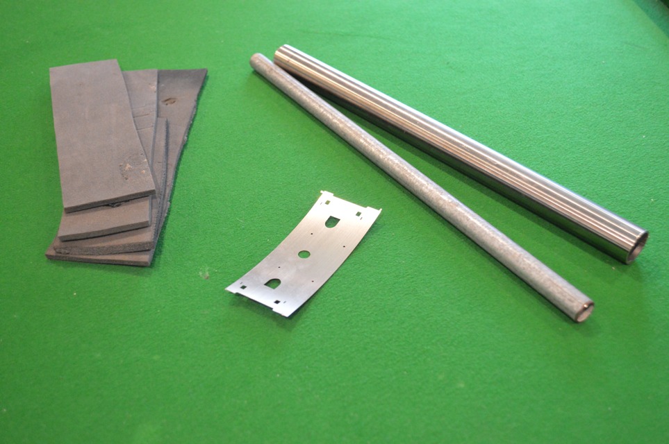
However I thought about this for a while and decided that the problem was with the surface that I was rolling the sheet into.  So I used instead of cloth a strip of the neoprene wet-suit material that I use to provide a springy surface for my trackwork.
Using this as a base, the next curve in the smokebox was maybe 20cm diameter, and adding layers of the squashy neoprene allowed a tighter radius to be made.  I had to use a smaller diameter rod as well (about 15mm) but in the end the 38mm diameter smokebox could be formed.  nerve-wracking, but satisfying in the end.
Small Smokebox and boiler 02
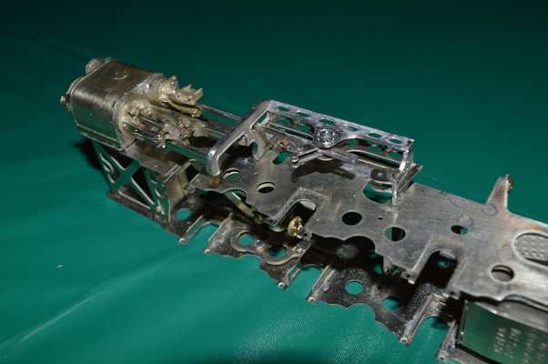
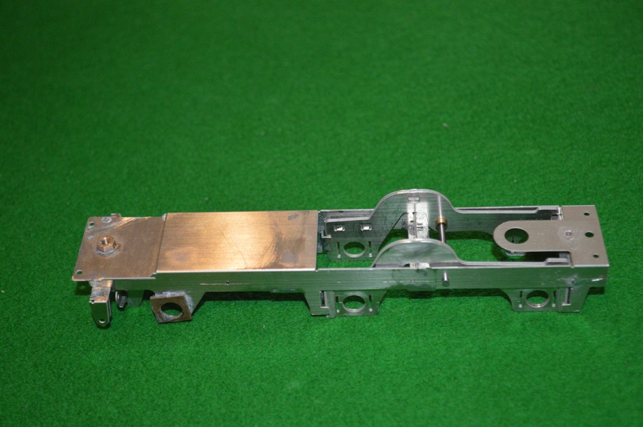
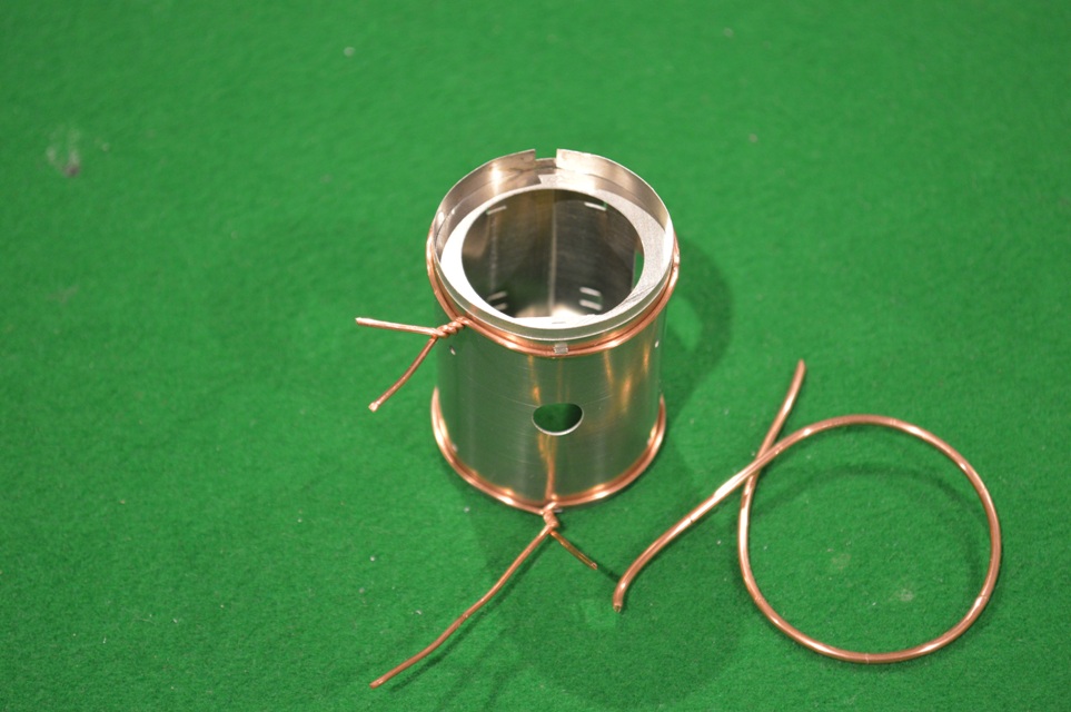
Having the formers to make the accurate cylinder was useful as well.  This picture shows the copper wire (from mains electricity cable) used to squeeze the inner cylinder of nickel-silver down onto the formers.  Thicker copper to hold it in place, then thinner copper to squeeze the metal down.
Small Smokebox and boiler 03
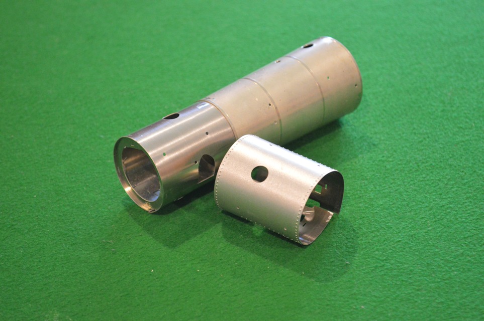
After that it was easy (relatively) and both the smokebox and the taper-boiler could be made accurately.
You can see in the above picture that I slightly over-did the curve on the detail overlay, but that did not matter in the end.
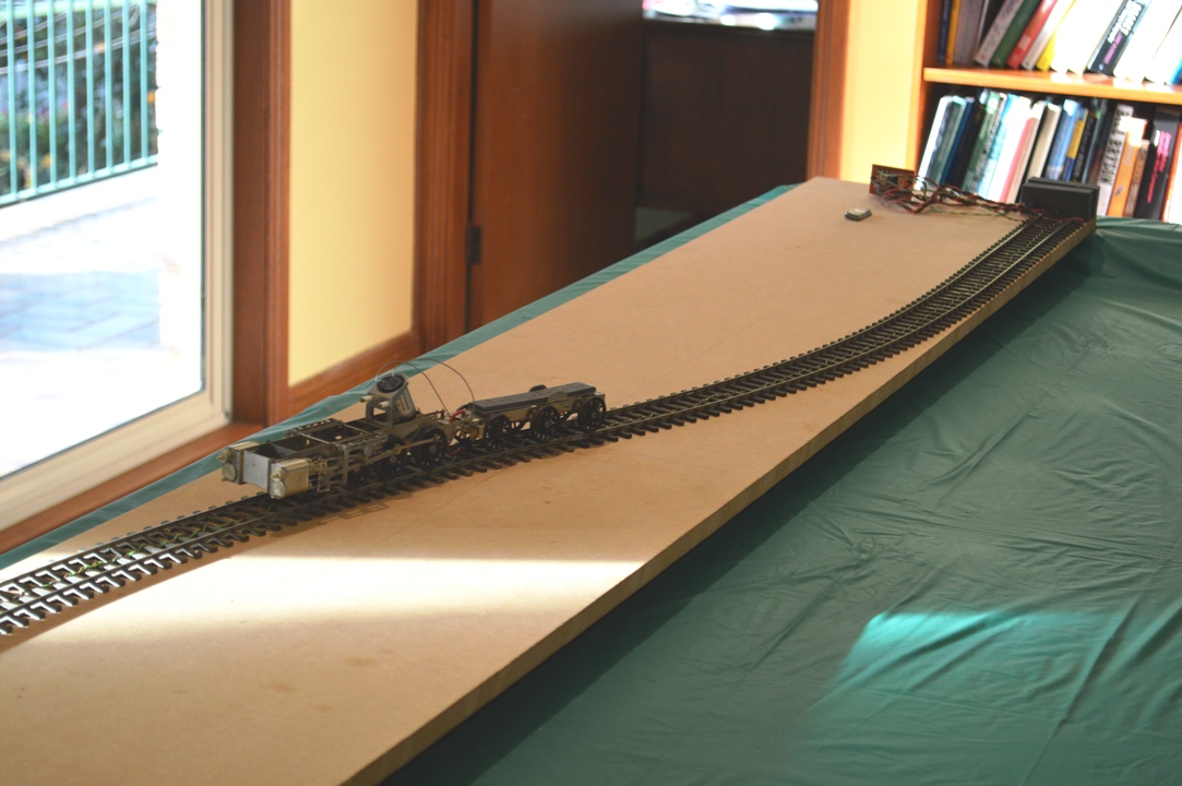
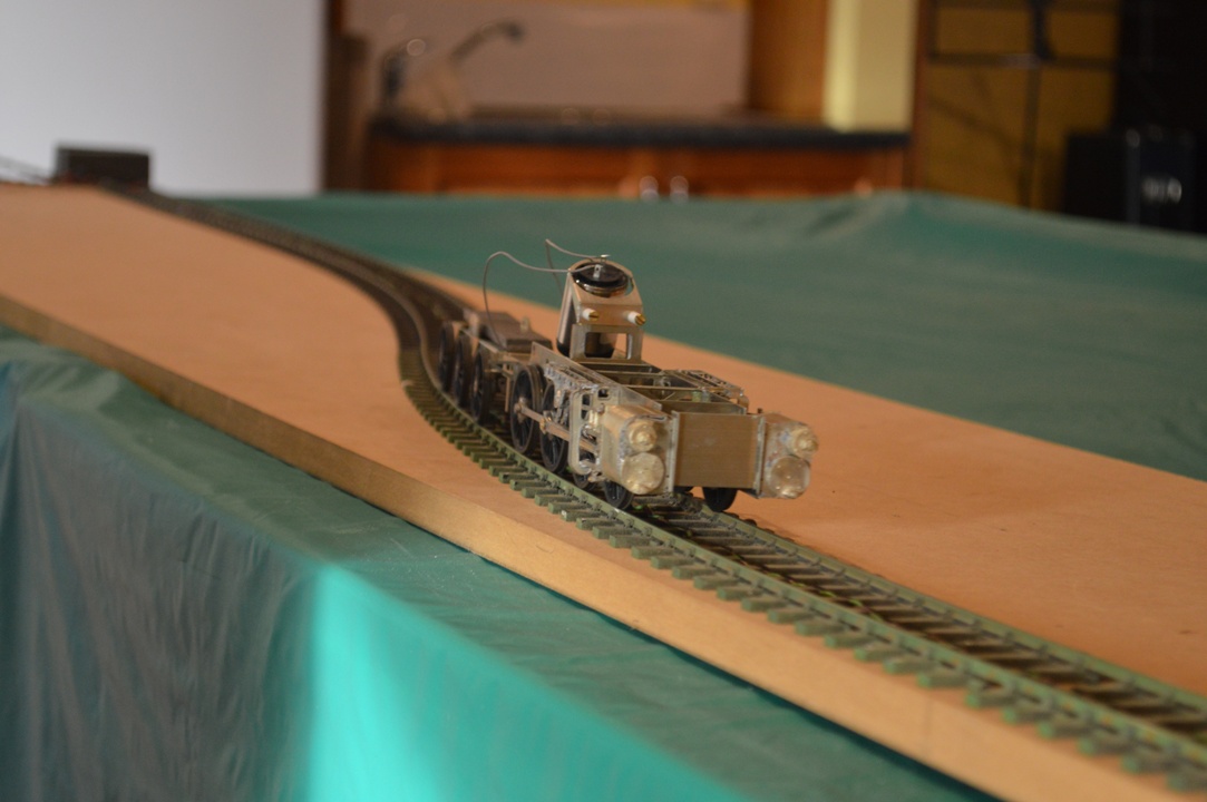
It is now, for the first time, possible to look at a preview of what this kit is going to be like when it is finished.  OK, I accept, it takes a deal of imagination still ….
attachFull46110
David

Walking in the Blue Mountains

Although we have lived in this area for twenty year (!) we haven’t really done much exploring on foot.  I think that there are a number of reasons for this: the two boys doing so much weekend sport, Sue’s and my (David’s) on-call, so many other things to do, which are more attractive for Sue, etc.  However last weekend and this one Andrew and I drove up to Katoomba and walked out in the direction of Mount Solitary.  Walking the the Blue Mountains is very different from many areas.  Here you tend to start high up, walk down into the valleys and then walk up again to the peaks.

Small Mt Solitary walk 01Last week we walked down the Furber Steps to the “Federal Pass” below Katoomba, and then walked around to the Golden Stairs.  At that point it was starting to get dark (we had started very late) so we walked up the Golden Stairs to the ridge and back to the car along a fire-trail.


This week we took up from where we left off, and parked the car at the top of the Golden Stairs, before descending into the vally and walking out towards the “Ruined Castle”, skirting around that rock formation before scrambling up to the western end of Mount Solitary.

This was a tough walk.  The scrambling over rocks to climb up to the summit was seriously tricky in parts.  Not rock-climbing, but demanding a lot of strength and agility.  We had an excellent day out.  Reaching the top of the mountain is so different to the UK: at the top is a camp-site in quite dense woodland – the tops are never clear of trees in the Blue Mountains, and although there are lookouts where pictures can be taken.

Small Mt Solitary walk 05This picture shows the route.  It is taken from the bottom of the stairs down: we started at the plateau top.  We then skirted around the cliffs seen and crossed via the bottom of the “Ruined Castle” – seen in the distance between the two cliff formations – before climbing up the ridge to the top of Mount Solitary – seen on the left of the picture.


Stanier 8F in S7 part 12: running the chassis for the first time.

The 8F is progressing well, and I have been able to fit the special parts and run the assembled chassis for the first time!

Small The first run on test track 1


It was a great moment to see it move for the first time.  After I cleaned my test track, it ran for the first time with almost no hesitation.


Small The first run on test track 2

I decided to try running it with the connecting rods in place but before I try the return cranks, etc.  I had to wait to try out the running until the tender pickups were done.

The third picture shows the tender pickups: the compensation mechanism is still able to work (I have left loops in the wires to allow this, but there’s still a lot of gear to go into those spaces, so I’m not sure how well this will work) and the temporary connections visible going to the loco. chassis on the right. The split axles can be seen.

Small Tender electrics

It doesn’t look much like an 8F, and the motion isn’t all connected yet but it shows that the tender pickups are working and that the assembly so far is acceptable.

It runs better forwards than reverse at the moment, but goes reasonably smoothly at 7V drawing 100-200 mA, and it’s still running without any lubrication.

S7 Stanier 8F Part 11 “Obtain a running chassis”

The instructions are a little terse at times, such as this: “Obtain a running chassis” !

Small Obtain a running chassis 01

After a struggle, this is where I am now at:


Motion bracket, etc., in position on the frames.

Motion bracket, etc., in position on the frames.

However it will take a little while to describe how I reached this point!


This is what I had constructed so far:

I had bought the special ScaleSeven wheels, but it turned out that  the wheels rims/tyres had been made to S7 standards, but the central boss part of the wheels was far too thick.  I was lucky once again to be able to enlist Richard Davidson’s help, and he used his lathe to thin down the wheel centres by about 0.5mm each.  This extra space on each side would be crucial to allow the wheels and coupling rods to turn behind the slidebars and crossheads without catching.  Even with the wheels thinned down, it is a very tight fit.  It was simply not going to be possible to fit the manufacturer’s crankpins, washers and nuts.

Wheel BoltOnce again, Richard has been the saviour.  He manufactured four specials crankpins – bolts to go through the coupling rods from the outside.

I decided that on the first axle the special crankpin could be used without a washer inside, as the coupling rod was slightly thicker around the crankpin, giving clearance over the wheel centre.  For the second axle, though, a washer would be needed between the special crankpin and the wheel boss, as the articulation in the coupling rod would foul the wheel centre otherwise.  For the third and fourth axles the Slater’s crankpins could be used.

Small Annotated Obtain a running chassis 02Shown here are the different crankpins in place.

When I first put the axles in the frames, bolted the retaining plates to keep them there, attached the coupling rods loosely and turned the chassis over: JOY – the chassis could be pushed forward and the wheels all rotated with minimal binding.  Too easy, as they say here in Aus.

“Too easy” in fact ….  Once I tightened down the crankpins the binding started.  I am not sure what the correct way to sort this out is, but Richard had once shown me how to push the frames along, and when the wheels stopped rotating, move each segment of coupling rod sideways with a pair of forceps to see if it moves: even a little movement shows that this is not the part which has stuck.  When a crankpin with no movement is found, the hole in the coupling rod probably needs to be enlarged (with a small tapered reamer).  I slowly opened out the holes in the coupling rods where the binding was occurring.  At least with the articulated coupling rods this is made easier.  However it also became obvious that on one wheel the countersunk central bolt holding the centre of the wheel to the axle stood out too far and was scraping against the coupling rod – the bolt had to be filed back just a little.

This all seemed to take ages, and the special crankpins were difficult to take out each time – I had to buy a “pin chuck” (like a very small drill chuck) to hold the circular heads of the crankpins.  However in the end I did “obtain a running chassis”, although one without the connecting rods, etc in place.  I couldn’t then resist a trial fitting of my Portescap motor and ABC gearbox, to see it all turn for the first time!

Using the Slaters crankpins and their “top hat” bushes made the coupling rods stand out an unrealistic distance from the wheels, so next action was to thin down the flange of the top hat bushes (almost removing the “rim” of the “top hat”!), and shorten them so that they are only slightly longer than the thickness of the rods.

Small Obtain a running chassis 03After all of this, fitting the cylinder/slidebars/motion bracket assembly revealed that all the work was being rewarded, with a small but definite clearance between the front crankpin and the crosshead on the slidebars.

The connecting rods were still not fitted, so next was to attach these to the crossheads.  There was nothing in the instructions about how to do this.  There is a post coming out of the recess in which the small end of the connecting rod fits, about which the rod will move.  I cut this off flat with the crosshead rear (the was no way it could be allowed to protrude!).  After some thought I measured the post: 2mm diameter, and made two tiny circles of flattened nickel silver wire (curled around a 1.9mm drill, then flatted between a steel ruler and a granite benchtop with a hammer (lucky the household manager was out again).  I could then solder the wire circle around the post to hold the connecting rod in place.

Small Obtain a running chassis 05Connecting the connecting rod then allowed me to see the next difficulty – the expansion links have to be made very carefully so as to hang just wide of the connecting rod.  I had not done that (it’s not easy to see this difficulty before this latest part of the construction), so some reconstruction is going to be needed now.


S7 Stanier 8F part 10. Curving the tender sides.

I have started on some of the bodywork for the tender. For someone like me, this threw up some significant difficulties due to my lack of expertise: how to bend the top edge of the tender sides? I have bent sheet metal before, to make the Belpaire firebox of my industrial Garratt, but this was brass, and not a particularly wide sheet of metal, either. The nickel-silver sheet for the tender side requires an even bend along a length of about 11cm. Dave Sharp from MOK has instruction about how to do it, but they are sketchy. The bend covers a height of about 3.5mm in the side, so I worked out that as the bend was through about 45 degrees, a bend of about 8mm diameter would be about right [8×3.5=28mm, divided by Pi = approx. 8mm diameter].
Small Bending the tender sides 01The instructions show how to draw lines on drafting tape inside the bend, to position it accurately. This is good, but how to make the bend? My first try was to place a slightly smaller diameter drill to bend around, and clamp the tender side in my big vice.

However I simply couldn’t bend the nickel silver!
In any case, the drill wasn’t really long enough, and the ends might not bend properly. I was talking/e-mailing Richard at the time, and he suggested I buy a longer rod, of slightly smaller diameter than the bend I wanted to make, and then either roll the sheet over the rod using a rigid metal plate to transmit even pressure, or clamp the top edge of the tender side in the vice and bend the body over the bar. I suppose it was a little foolish of me to try to do it the other way around, but somehow it seemed right to bend the bit that is supposed to be bent, rather than bending the body down whilst holding the part which is supposed to be bent, upright in the vice!
I started to try to bend the sheet over a piece of 1/4 inch (6.3mm) aluminium rod which I found, on our granite kitchen benchtop (the household manager was out), but it was very difficult to bend, and also I thought that this technique might not produce a discrete bend in the flat sheet of the tender side (if you see what I mean), but rather make it a nice continuous curve in the metal sheet. It was impossible to hold the rod still relative to the sheet metal whilst trying to make the bend.
Small Bending the tender sides 03So, back to the vice. The trouble now was to hold everything at once, to allow the rod and the tender side to be exactly positioned. So I used masking tape to hold the rod against the aluminium angle used to make smooth jaws in my big bench vice, as shown on the left.

Small Bending the tender sides 04

Then I put the tender sides into the vice and could adjust the position so that the start of the curve was held in between the rod and the vice, the other end of the curve being above this (in the picture one can just make out the second line):

This finally allowed me enough leverage, using a thick rigid steel rule, to make the bend in the tender sides.
Small Bending the tender sides 06

Small Bending the tender sides 05It also allowed me, using the same technique, to form the vertical curves at the front of the tender sides (a bit out-of-focus in the picture, sorry).

HAPPINESS !

David

S7 Stanier 8F Part 9 Initial stages of the tender

Whilst waiting for parts needed for the main locomotive to come from the UK, I have started on the tender.  The model kit is designed to have a “compensation” mechanism, which allows the rear two axles to move up and down independently.  The front axle is fixed.  This is shown in the picture below.

Small Tender compensation mech 1There are two inner plates which rock about the bar which can be seen crossing between the frames.  On each plate there are two “loose links” which carry the axle bearings, and allow the axles to move at small angles in the plane perpendicular to the axis along the tender.  The loose links are not shown in the picture.

These loose links I have had to modify anyway, to take double-sided circuit board, as part of the adaptation which will allow the wheels to be isolated from the frame, and allow electrical pick-up through a “split-axle” design.  On the picture above, for the fixed axle at the front of the tender I have already soldered on the circuit board [it is not exactly straight, but this will be unseen and unimportant when the model is complete].

Small Insulated Loose LinksThis picture shows the loose links adapted with circuit board.  The left-hand one has the double sided circuit-board soldered to the link.  The loose links will have the side parts bent back at right-angles and slid through the slots seen on either side of the bearing holes in the rocker arms seen in the top picture.

The central loose link, seen with the c-b underneath, has had the loose link bored out with a countersink, which then allows the brass bearing to be inserted from the other side, remaining electrically isolated from the surface on the side closer to the camera, which will be in contact with the frame of the tender.  This is seen on the right hand loose link.

Small Isolated bearingsThis way the wheels and axle are isolated from the frames although firmly fixed to the loose links, or main frames in the case of the fixed front axle, seen here.

Fortunately S7 wheels have a wider back-to-back measurement than normal Finescale 0-gauge wheels, allowing the insertion of the c-b.

It is all a complex way of allowing the rear two axles to rock independent of each other.  I hope it works, with all the modification to take my split-axle pickup method!

Meanwhile the wheels and other items have arrived from England, and I have been able to put the coupling rods, driving wheels and hornblocks all together into the locomotive frames.

Small Wheels and Coupling rodsI was not looking forward to this stage, actually, because of my previous experiences – two 0-4-0 locomotives and an 0-6-0, all of which I had problems with at this stage.  In all three cases the coupled wheels had suffered from a lot of binding as the wheels went around, presumably because the coupling rods had slight different distances between the crankpins to the distances between the wheel centres.  So the thought of all the adjustments necessary on an 0-8-0, and the enlargement of all the coupling rods crankpin holes was not pleasant.

This kit is in a different league.

I put it all together, turned it over, pushed the frames forward, and the wheels rotated perfectly.  No binding.  Even without any additional weight on the frames.  MOK clearly have made the kit with perfect dimensional accuracy, although the correctly articulated coupling rods may help also.  Whatever it is doesn’t really matter – it works!

Look carefully on the picture of the frames and you can see the 14BA nuts to be used to put the keeper plates on, to hold the hornblocks in place.  14BA is small, and MOK suggest 16BA!

Tasmania

Sue and I are now “Empty Nesters”, by which I mean for the first time in nearly twenty years we don’t have children to look after.  This last weekend was a conference for Sue in Launceston (north-central Tasmania) and I could go along as an Accompanying Person.

Small Launceston 01


So whilst Sue was in the conference, I could go walking in the Tasmanian forests near Cradle Mountain, as shown here.

Tasmania for me is very like the Lake District in England – wet, fertile, lots of mountains and cool (by Australian standards).


Small Launceston 03


I went walking up through forest to find this waterfall.  It was very like walking in The Lakes, except that on this day in early Autumn, I could do a two-hour walk and not meet another person.


The following day I went up to Beaconsfield, where there used to be a gold mine.  It closed a few years ago, shortly after there was a well-publicised mining accident when two miners were trapped underground and only rescued after a truly spectacular rescue effort.

Small Launceston 04There is now a mining museum there, well worth some time spent looking around.


Small Launceston 05They even had a well-restored traction engine.


I also spent some effort to get right up to the north coast of Tasmania, up to a point called “Low Head”.  There they have a restored lighthouse, and evidence that nerds occur even in Tasmania: a group of enthusiasts have restored the Victorian-era fog-horn from the lighthouse.  It is apparently the only one of these “precision instruments” still in working condition, anywhere in the world.  If you would like to hear the “famous Groan-Grunt” of this foghorn, a volunteer is there to set it going every Sunday at noon.

Unfortunately, I couldn’t wait ….

Scale Seven Model Stanier 8F Locomotive Part 8 – the wheels

Small Slaters S7 8F wheelsThe Slaters Wheelset has arrived, and very nice it looks too.


Coupling rods (articulated as shown), crankpins and crankpin bush

Coupling rods (articulated as shown), crankpins and crankpin bush

They come with an innovation (to me) from Slaters: crankpins which can be screwed into a boss set on the crank.


However Small Crosshead and S7 8F wheelsfor wheels on an S7 version of the MOK kit, they create a problem, illustrated in this picture:

The crankpins are clearly too long in this case, and their rotation will be obstructed by the crosshead and slidebars.
Now I am familiar with this problem from when I widened the frames and cylinders, etc., for my S7 Industrial Garratt, and actually this doesn’t look quite as bad as that one did. However I will need to shorten the special crankpins made by Slaters (if you look closely I will need to cut them back to move a bit more that the threaded part of the pin), and then I will need somehow to reproduce a thread on the end of what remains.
With the old Slaters system it would have been easy, but here the crankins are completely different.  The part threaded to go into the boss in the wheel is 10BA.  The smooth part of the pin, to go inside the coupling rod and connecting rod bushes) is also 1.6mm O/D, but the retaining nut screw-thread is 12BA.

After seeking help from the experts/enthusiasts on the WesternThunder website, below is my first plan [I suspect that this is destined only to be the first plan]. The picture shows the frames with wheels in place. The front end is on the left. I am going to take advantage of the special construction of the S7 wheels, with the 10BA tapped holes for the crankpins.

Coupling rods and crankpins 02

I am lucky in having my friend in Melbourne Richard Davidson who has done some work on his lathe for me. Below the frames in the picture are the special crankpins which Richard has made for me.
My illustration shows how I hope to arrange the crankpins. From the front: axles one and two have the special crankpins in place. Axle one the pin is part-way through the coupling rod. Axle two has the crankpin all the way home. Axle three and four have the Slaters crankpins. The ones for the connecting rod wheels are longer, and will take two brass bushes on top of each other, through the coupling and connecting rods. The final axle will have a standard Slaters crankpin and bush.
Clearances will remain extremely tight at the front end. I intend to try the front crankpin fitting direct to the wheel without a washer. The boss on the coupling rod is slightly thicker than the body of the rod itself, so as it goes round it should be clear of the central wheel boss. The second wheel will need a washer, though: the articulation of the coupling rod will catch on the central wheel boss otherwise. By the third axle, fortunately, the clearances should be less critical. So the flat portion of the Slaters crankpin, acting as a washer, will be less critical.

I hope that it all works …..

Norfolk Island

We have just returned from Norfolk Island.

We spent ten days there.  It is an unusual place, Norfolk Island familybeing part of Australia and NSW, but being an “overseas territory” and so not governed by many of the laws of NSW: it is duty free, there is no income tax, and other anomalies.  On the other hand, the currency is Australian Dollars, and the population are Australian citizens.


Norfolk Island convict buildings

There is a historical interest on the island, in that it was a penal colony, and after that use ceased, it was the final destination for the descendants of the sailors involved in the mutiny on HMS Bounty.


Norfolk Island convict gravesWe spent some time looking around the old buildings, and even the graveyard has some interest, with the headstones showing signs of beingmade by people who had difficulty spelling and certainly amateurs at spacing out he letters on the stones!


The best parts of the holiday, though, were such things as going on a day’s course on how to prepare restaurant-standard meals.

Norfolk Island golfAndrew and Nick had a couple of golf lessons and played their first couple of rounds of golf.


Norfolk Island Emily Bay

We also spent some hours swimming in Emily Bay, a beautiful place to swim: and omega-shaped bay, with coral reefs across the entrance.  So no surf, gentle waves, and excellent snorkling to be done.  My (David’s) swimming improved greatly.  I swum further than I have ever done before: more tha 250m!  It may not be very far, but to me this is a triumph.