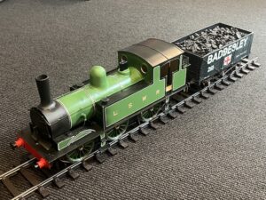
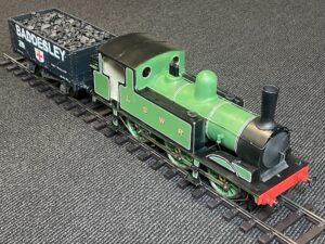
LSWR G6

I realise that as a narrative of building this model, my entries have not been good. 

The model comes as a set of parts with mild steel frames and a mixture of brass and nickel silver sheets cut into parts, plus 3D-printed plastic (nylon?) detailed parts.

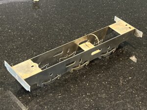
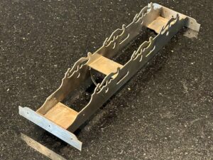
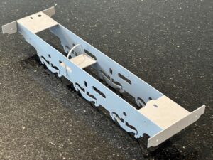
I started with the laser-cut steel frames, and used “silver-solder” to put them together, trying to make them exactly “square”.  Silver-soldering steel is outside of my previous experience, but seemed to go reasonably well.  Original post is in <Miscellaneous, incl. Rashmi’s wedding>.  The main issue (discovered later) is that I didn’t adequately clean the steel of all the flux, which meant that I have had to face parts which were rusting!  Trying to work out what to do about this led me to treating the frames with a combination of sand-paper, dipping in strong vinegar, and abrasion with various tools. 

End result:


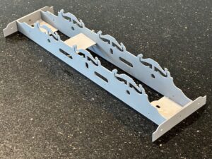
Once I had the frames back to bare metal, I had to start painting to lessen the risk of further corrosion.  Here the frames are in primer:


You might notice that the guard irons (Used to clear track in front of the wheels) have been removed.  I hadn’t realised that the two sets of guard irons had to be laminated before fixing them in place.  So I took this opportunity to remove them and correct my mistake.


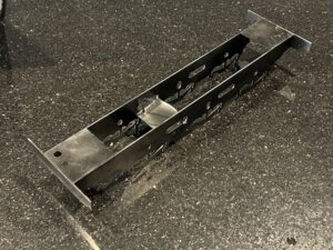
Frames painted black:


  Meanwhile I had to decide what colour to paint the loco., because it is recommended in the instructions that the boiler and smokebox be painted early, because access for painting would be very difficult.  I am generally an advocate of realistic appearances for models, and in the smaller scales I have done this.  However for this larger model I decided to go for an “as-new” appearance – in fact there is a photograph of a G6 in LSWR passenger colours complete with lining.  Even though the picture is black-and-white, i have decided to follow this historical record, although I my add a few soot and coal-dust stains, for realism.

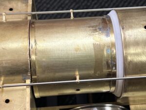
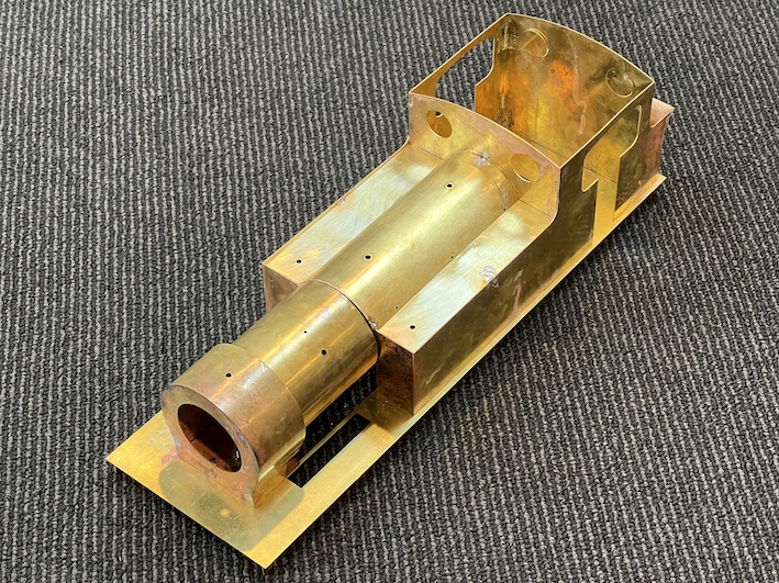
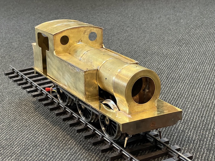
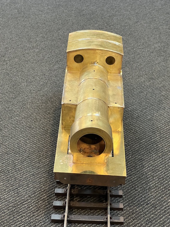
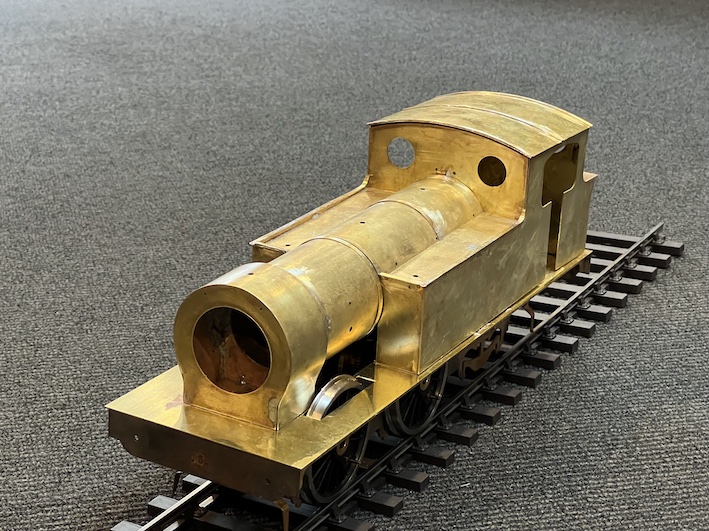
So I started to work on the body/water tanks/boiler/smokebox unit.  See <LSWR G6 Progress> ‘blog.  To make up the body unit, it is necessary to construct the main structure from sheets of brass, laser-cut to exactly the correct dimensions.  When it works, it’s very good, but when one misaligns something, the error can be magnified by the size of the part: see <LSWR Progress 3> to show how the boiler and smokebox don’t seem to line up once the boiler and water-tanks are put together as accurately as possible.  Frustrating, but a little filler will probably disguise the defect(s).

Meanwhile I had to make a decision about how this engine would move.  I decided to go for battery-powered radio-control.  Another “first-time” for me.  See See <LSWR G6 Progress 2>.  I bought an “”off-the-shelf” solution with a 50:1 gearbox Slaters power unit, and so far it seems to work well (see the <LSWR G6 Progress 2> entry) – at first I bought the wrong battery-pack, and the motor is a 24V one instead of 12 volts, but this turns out to be unimportant.\ and with some adjustments, all is well.

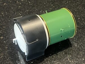
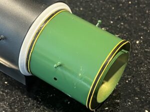
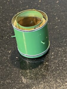
Now I am up to painting and lining the boiler.  The correct shade of green is automotive RAL6002, I have been told, and I have both black paint and a small pot of automotive “Sunflower” colour for the lining.  I have a German-origin HAFF bow-pen to do the lining (originally bought for my ScaleSeven Garratt model – search for “industrial garratt” on this website).


Looks pretty good on the whole, I think.  The white plastic moldings with be painted black eventualy.

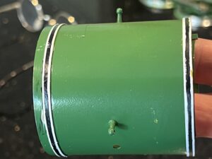
Here is the boiler section with the corrected lining colour(s):

.


These magnified pictures seem to show every flaw in my painting, but I think it will look OK when it is all put together.


LSWR progress 3

We have been away for a fortnight (in Uzbkistan – see the ‘blog) but I can now do some more on my G6.  Actually it is not going as well as I had hoped. 

The individual sub-assemblies seem to work OK and go together well; it’s just that the subssemblies seem not to align quite correctly.  As you can see above, when the boiler/smkebox and watertanks are put together, then don’t quite align and there are cracks.


On the other hand I can now put the handrails on.


Putting the handrails on proved quite a challenge: curving the part for the smokebox is difficult o get right. 


I have reached the stage where it may be necessary to start painting as I go along.  Once the subassemblies are united there will some little corners and areas under the boiler for instance, which will be quite difficult to get at by brush or airbrush.

I am hoping that one the various parts are united, and held together in various way, the alignment may all “come good”

LSWR progress 2

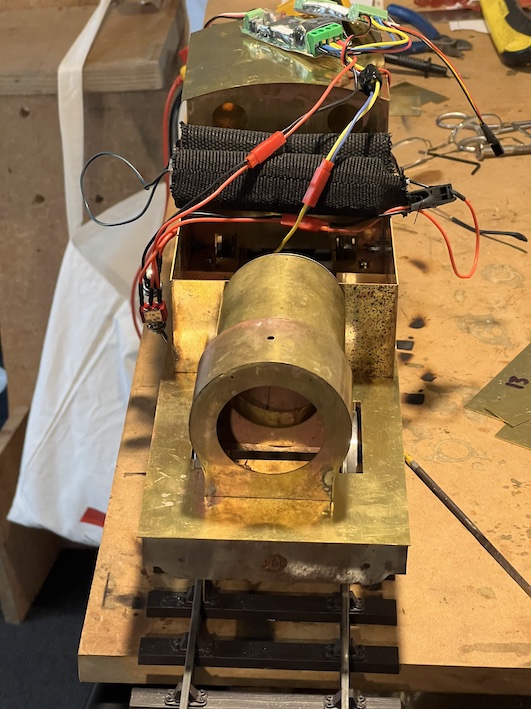
I now have the radio control apparatus, seen piled on top of the superstructure .


I have opted to have sound (!) as well as battery-powered radio-control.

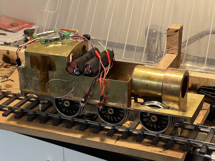
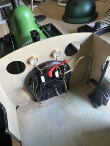
The battery-packs can be seen stacked on the outside edges of the side-tanks.  The speaker for the sound is in the cab at this stage.  The batteries will eventually go inside the water tanks.  So far the electrics all seem to work OK.

The kit is very well made from sheet brass (and steel).  This is so true that when parts don’t quite fit I first blame myself for not building it well enough!  So far I have had to use no molded parts, just sheet metal cut to size.  Mike Palmer, I think it is he who packs up the kits for the Gauge 3 Society, had taped parts together to aid their identification – important when several oblong bit of brass, or pieces of thin brass strip have to be identified before assembly.

I started off the kit by silver-soldering the steel frames (see the previous entry in the ‘blog), and have carried on using silver-soldering up until now – I love the way silver solder “flows” into the joints once they bare hot enough.  It’s also difficult to get the joints apart if you make a mistake though.  As you can see, progress on the body continues, and the engine is beginning to take shape.  Now that the main parts are done I’m intending to change to “soft soldering”, at a lower temperature, but I will have to se a large soldering iron, with a clean tip, as the large amounts of brass form a large “sink” for the heat.  That is, it’s difficult to get the work hot enough for the solder to melt and adhere.  I will need to use a better-cleaned tip on the iron than I am usually using.

The kit is very well thought-through, although in some ways this needs to be better explained than is done in the provided instructions.  Perhaps I’m too inexperienced at putting these models together, but it might have made things easier if I had understood a few central principles like the fact that the from part of the boiler is separate from the rest, but when it and the made-up water-tanks-and-cab section are held onto the footplate (with half-a-dozen bolts) it is all held together and in-line.

It is possible, now, to see the body mounted provisionally on the frames and wheels.  There IS something of a problem, though …

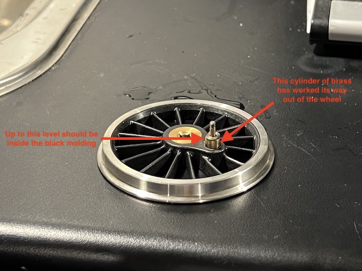
The rear wheel on the left side is missing!

I had put all the wheels in the frame, added the coupling rods and persuaded the whole assemble to turn under the power of the motor, using the radio control system and the rechargeable batteries I have bought.

After a while, though, it stopped, and on close inspection this had happened:

The mount for the crankpin had worked itself out of the black plastic molding which represents the wheel hub and spokes.  Disaster.  Can I get a new wheel from Slaters?  The trouble is that this would take weeks at best.  Can I just push the brass mount back into the wheel (and use cyano-acrylate glue)?

I suppose that whatever I do, at least I can get on with the bodywork …

LSWR G6 progress

LSWR is only one letter different from LNWR after all …

I am constructing an LSWR tank engine in Gauge 3 because basically it is the only locomotive available for this scale at a reasonable cost with the necessary attributes: a good scale representation of the original, electrical propulsion but with radio control, and a scale model of an engine which is not too large.

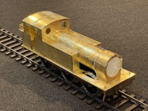
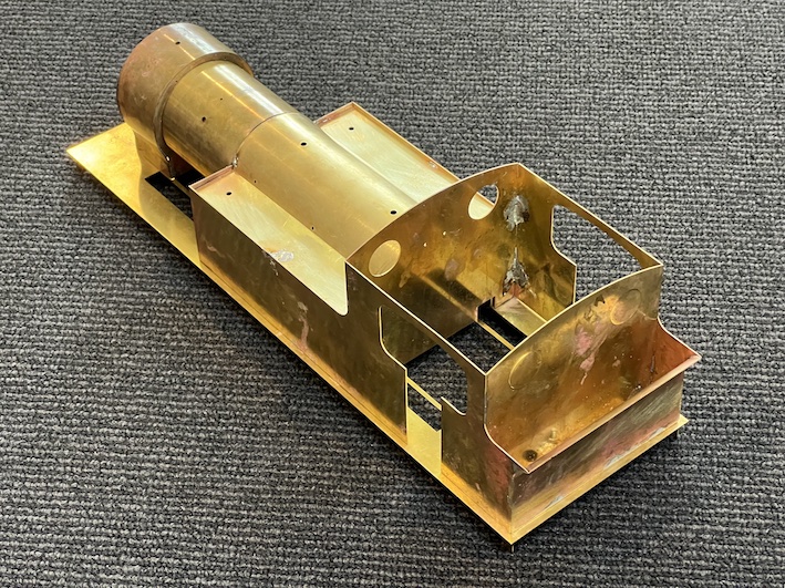
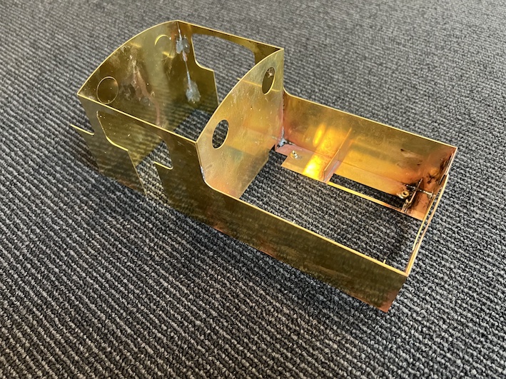
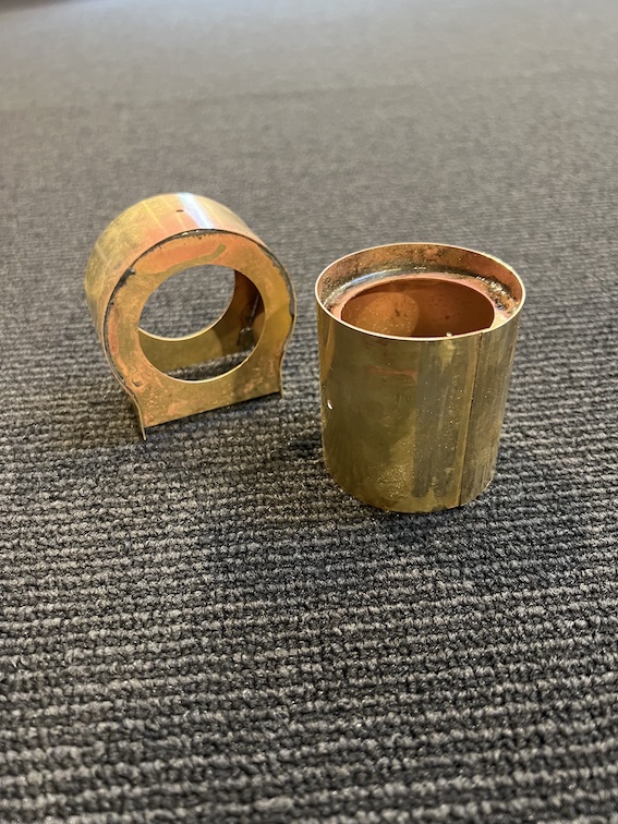
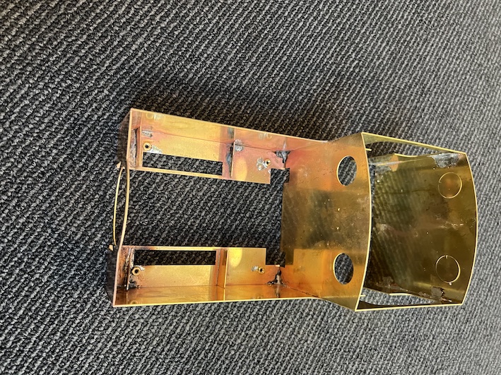
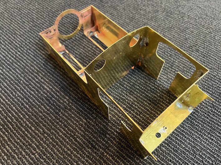
Fortunately, the Gauge 3 society has produced a model kit which fills these categories/criteria.  A scale model of an 0-6-0 tank engine which was used for shunting and light traffic.  Here are some pictures of the kit as I start to make the body of the lodomotive:


The frames I have started on already (see the entry “Miscellaneous, incl. Rashmi’s wedding”, but now I am starting on the main part of the engine – the boiler, water tanks cab and coal bunker.  The kit is largely in brass sheet, about half a millimeter thick.  As with the steel-sheet frames, I am trying to use silver-soldering for the major joints, thinking that later construction will be made easier if I use (lower temperature) “soft soldering”.

So far it has all gone well.

Miscellaneous, incl. Rashmi’s wedding

We recently went to Rashmi’s wedding.  Rashmi is Andrew’s oldest friend apart from Nick.  She joined Andrew at St Paul’s Grammar school at about age 16/15 respectively and they have gone through the IB exams together, medical entrance exams, medical school and being interns and residents together.  Their academic rivalry was probably why both achieved 45s in the IB (the top mark) and both were well into the top percentile of the application to UNSW Medicine.

An old joke has been that whoever married Rashmi got Andrew as part of the contract …

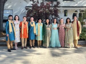
This was (another) spectacular Indian Wedding, and most of the guests wore suitable clothing.  Here is a picture of Andrew and his friends at the wedding.  What a truly. multicultural event!  Backgrounds are Indian, Chinese, European, Phillipines, but all are Australian.


I’ve started to build another railway engine.  This time in Gauge 3 (the same size as my Dyak live steam locomotive) and so twice the size of my previous builds in Scale Seven.  This will be very different – battery powered and radio-controlled.  Gauge three is the scale of the wagons which I have built (see the Baddesley wagons blog and other previous entries) and this is for a long-awaited garden railway in Glenbrook.

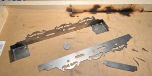
I’m having to learn new skills, including silver soldering.  The frames are steel and the silver solder is much stronger than “soft solder”.  THe operator usually has to use a (small) blowtorch as the source of heat

So Far, So Good.  There’s a 20c coin (about the size on an old penny) to give an idea of size – this 0-6-0 tank engine will be over 40cm long.  The scorch marks on the wood are because the advice is to use a “jig” of wood constructed to be at exact right angles to clamp the frames and footplate to before blow-torching them up to temperature.


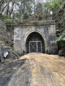
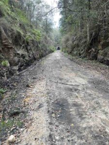
I’ve also been exploring the eastern end of the old Glenbrook Tunnel again as the local council prepare it for use as a cycleway!  They have done a lot of clearing up, as you can see here.


Finally, this is a view of a pair of kookaburras in Euroka Clearing when we walked down there recently.

The are wonderful birds.


Baddesley wagons

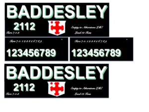
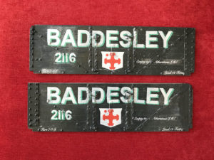
I had some wagons to make in Gauge 3.  Coal wagons to a particular design, chosen by me on the grounds that they were relatively easy (! – see later) to make, and were colourful to make them more attractive.  Also, they are to a design compatible with my unlikely-to-come-true ambition of making a “William Francis” industrial Garratt locomotive in Gauge 3.  The trouble was or is, that no-one makes the relevant transfers in the right size for Gauge 3.There was no way I could free-hand paint the designs, so I had to think of a way to get transfers made.  If I could produce a computer file design, perhaps I could persuade POWSides to make the transfers (though at what cost, I hesitate to think).My first try was to do the whole side at a time, black background and all.  However on-line advice suggested that this was not a good idea, and a guy called “Overseer” on the website offered to do some transfers for me if I could do the design work, which included making files where all the white lettering plus the background is coloured black instead!
The reason for this is that it is possible to buy transfer sheets to go in an inkjet printer, but printing onto them is not straightforward, as they are clear backround sheets, and printers are made to print onto a white background.  So in order to produce the correctly-coloured letters it is necessary to print the letters first in white, then overprint the relevant colour a second time through the ink-jet printer, hoping that the paper is in exactly the same place a second time through. White is not a usual ink-jet colour, so the black cartridge is changed for a white-ink one, and the “black” printing done in white!
Fortunately we have a friend locally who is a graphic designer, and he was able to produce the relevant computer files of single-colours only, and I sent them all to “Overseer”.
Eventually the process was done, and I could try the transfers out.  There were a number of defects, but overall it was a very pleasing result. The number was angled, and the application of colours one on top of another was very difficult exactly to position.  Overseer sent some transfers in single colours as well as overlaid colours.  To try to position TWO colours (red and green) exactly onto the background white with the printer is clearly extremely tricky. 
The raised detail on the wagon sides was clearly a problem for me also.
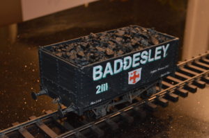
Anyway, here is a view of the first complete wagon.
Many thanks to Overseer, who made the transfers, my friend Chris Burns who did the drawings, and of course Mike Williams who makes these kits.
It’s not weathered as yet.
Now I just need an industrial Garratt to pull it.
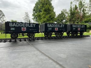
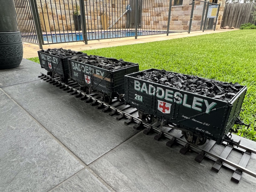
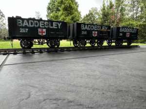
A long time coming, over a year, but here is the rake of three Baddesley Colliery coal wagons.There is a story as to why it’s taken so long, and why they are in different state of repair of course.
2111 has clearly just come from the works after an overhaul.


2116 has clearly had some sort of accident, and has had to have a plank replaced.However overall I am very happy with my little group of wagons. I’m quite proud of the end result, although I think more “weathering” is needed to be at all realistic.


Here is the story behind a couple of the wagons. Even if it doesn’t reflect well on my common sense, there may be some lessons in it.
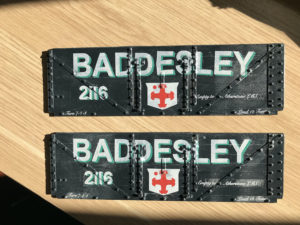
I started off to build the two wagons as 2116 and 2117 together, as I had two sets of Baddesley transfers to use and two of Mike Williams kits. Building the two at the same time turned out to be a mistake: you see Mike had inadvertently put three of one side in and one of the other when he sent me the kits. Unfortunately I didn’t notice this, even when painting them, and even more extraordinarily when putting transfers on! So although 2117 was OK, spot the trouble with 2116! By this time I had run out of transfers. I’m absolutely sure Mike would have sent me a new side if I asked (even to Australia!) but that was no use to me as I had no transfers left. So I thought about what to do, and decided to butcher the kit and I cut the ends off one of the side-pieces and reversed them, using Araldite and “Milliput” to try to correct the catastrophe.

Not perfect for rivet-counters, and clearly likely to be a little fragile, but in the circumstances not too bad I thought. A little while later:


The next problem which I created for myself came when I tried to Araldite the sides onto the underframe. It wasn’t quite square when the glue set. Not good, but recoverable I thought. Araldite melts, or at any rate loses its grip, somewhere between 50 degrees Centigrade and boiling point, in my experience. So I waited until the household manager was out, and used her oven to heat the whole wagon up progressively towards 100 degrees, thinking to re-stick the sides. The sides weren’t too far out anyway – so I used rubber bands to maintain some of the square shape.

Catastrophe! The whole thing came apart, and the resin warped with temperature so much (the elastic band didn’t help I guess) that the sides were badly distorted and the ends nearly bent back on themselves! “Don’t try this at home, viewers”.
Much anguish and thought later, and fact that the manager was still away, allowed me to use the oven and a pair of surplus flat bathroom tiles to straighten out all four sides and ends, plus the distorted underframe.

So in the end, the appearance of 2116 could have been much much worse. The wagon was put back together but now I saw that one of the transfers was distorted anyway, so I decided to “weather” the wagon, and paint it to look like one of the planks had been replaced but not yet painted.

Good recovery, I think.

Sydney Live Steam Locomotives Society

On Saturday I had another excellent day at the SLSLS grounds in Ryde.

I started off spending a while using my brushcutter to get rid of a lot of overgrown grass and other plants impeding progress around the elevated track [which I will need in a fortnight’s time if I can get to the “Smaller Gauges Open Day”]

I was then able to get my steam engine through both its “hydraulic test” and its “steam test”, which means that it is certified as safe to use in the future (4 years in theory).


We then tried to run my engine around the circuit.

The trouble was, I had forgotten to put the “steam oil” into the oil supply for the cylinders, so it lost steam constantly, and after about 100m “I ran out of steam” – literally.

However this disappointment was lessened by my being given a chance to drive the 3½ inch gauge “Britannia”, which was also having its steam test done.

It is a much bigger model engine than mine and as such is very “forgiving” if you are an inexperienced driver (!).


I drove it around the circuit a couple of times – really special !!!!


Making a switch (a point) in Gauge 3

This is serious nerd-iness, so look away ….                                [updated 15th March]

I wish to make a track upon which to run my trucks and Dyak, and whilst straight track is OK, I will also want some junctions.  Now this is an example of a British inaccurate sense of superiority and better command of language, over the New World (!).  In America, just like in the automotive world the word for what Brits call “bumpers”, they more accurately call “fenders”, and the components which Americans call “dampers” (because they damp down oscillations in the springing of car axles), the Brits call “shock absorbers” – which is not what they do at all.  In the railway world, the junction parts where a train can change tracks is called a “switch” by North Americans (accurate and descriptive) whereas I was brought up to call the same thing a “point” – what is the sense, or point, in that?

To get back to the point, I bought a kit to make the switch from a guy called Cliff Barker in England.  (sorry!)
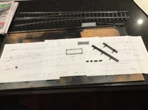
It comprises a plan, lengths of rail, rail “chairs” (for the rail to sit in), “sleepers”, or “ties” as the americans call them, and instructions.  At the top of the picture to the right can be seen the switch as I have made one so far.

OK, OK.  I will call the switch a “turnout” as a compromise, and the ties will be “sleepers” – although why they are called this I really do not know ….

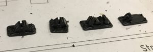
Here are some of the rail chairs.  Left-to-right are standard rail-chair, and narrower one for tightly-spaced rails (called a “bridge chair” for some obscure reason), and double chair for the check rails (see later), and a slide chair (ditto).
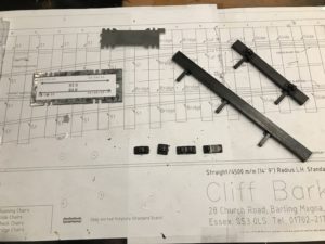
This is a closer view of the plan and the parts.

The instructions suggest that the turnout is largely built using the plan as a definitive guide to positioning the parts, but using my experience for ScaleSeven, I disagree, as will become evident later.

There is also a rail gauge – a device which sets the correct width between the tracks. – you can see two in the picture: the nicely made one from Cliff Barker, and the cruder one cut from a flat piece of steel by myself – with paper stuck to it to show what the actual dimensions are.  Not always quite what they are supposed to be!
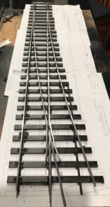
Here is the first one I built: a 4,500mm curved “turnout”.  I’m now onto doing a 6000mm one.

The instructions from CB suggest building the turnout mainly relying on the printed plan.  A problem with that is that this does not guarantee that the distance between the rails is accurate.  In straight track the distance between the inside edges of the two rails should be 63.5mm (exactly 4 foot eight-and-a-half inches or Standard Gauge, scaled down).  On curved track this has to be widened slightly to stop grinding of the wheels on corners.  Up to 64.5mm on curved track.

In turnout construction/pointwork this is crucial.
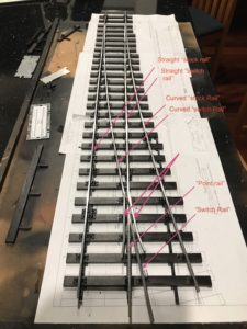
It is also difficult to follow the nomenclature of the turnout’s various bits of rail: see the diagram.  Click to enlarge.

IMO the best way to construct a turnout and get the gauges correct is to glue the straight “stock rail” down first.  The ties are plastic, and methyl-ethyl ketone (“MEK”, or plumbers welding compound) is used to weld the railchairs to the tie-bars/sleepers.
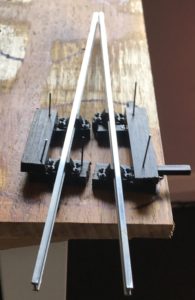
 

It is then necessary to weld/silver-solder/soft solder the point rail and the switch rail together, at the correct angle (tricky). On the left is the “jig” I have made to help with this: four rail-chairs are used to hold the rail (at the correct inclination).  The chairs are stuck onto offcuts of sleepers/ties and arranged on a flat piece of wood at the correct angle for the switch.  The rails are bent and filed to the correct profile then silver-soldered (it could be soft-soldered, but the silver-soldering will be stronger).
When I made the first turnout I followed instructions to position and stick down the curved stock rail after the straight one, fitting the switch/point V-constuction in between.  The problem with this approach is that acheiving the corrrect rail gauges (including gauge-widening for the curved rails) is very difficult.  In fact I had to take some of the railchairs off the sleepers to adjust their position – very difficult as they had been “welded” together!  Constructing it progressively from the straight to the curved side makes setting the rail-to-rail widths easier, I believe.
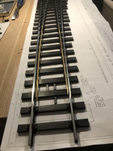
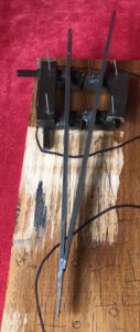
Before one starts sticking the rails down, however, it ts wise to shape/file/machine the “stock” rails – the long ones on the outsides of the switch – to allow the point blades to direct the wheels smoothly one way or the other – see the picture, taken from later in the construction, but which shows how I chose to make “joggles” (as Cliff Barker calls them) to allow for the point blades effectively to be recessed into the running rails. By bending the rails outward about 10-15 degrees, then at a short distance further along (CB suggests just 8mm) bending the rail back into line, the minor bend is made which accommodates the point blade.

An alternative is to file recesses into the running rail, but this is more difficult.  It is good to remember to make mirror-image “joggles”.  I did not, but as I was making two or more turnouts it didn’t really matter!  Clear thinking before sticking the straight stock rail down to the sleepers/ties is needed, but this is the first thing to do.  The printed plan is useful to space out the sleepers at this stage.
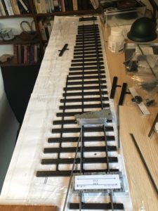
So position the V-shaped point/switch rail construction at the correct gauge from the straight stock rail and the correct position along the whole plan, with regard to where the curved stock rail will be.  It is helpful to shape the curved stock rail approxiately beforehand to allow the positioning of the V-shaped point/switch rail construction.

In my experience it is best to position the straight stock-rail to V-construction at the correct gauge first.  Put simply, I construct starting at the straight stock rail and then work towards the curved side, using the plan as a rough guide only (especially useful for bending the curved switch rail). 
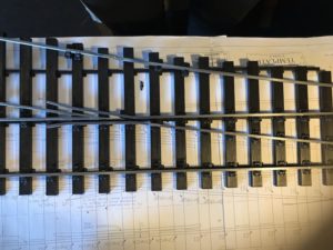
Next are the curved, then the straight switch rails.  Both “switch rails” need to be bent to include the “wing rails” which go on either side of the V-shaped construction. 

The “switch blades” are machined rails narrowed down to provide the narrow blades redirecting the wheels straight on or into the “turnout”
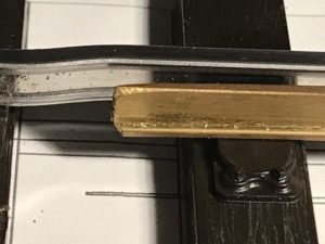
To the left is the picture showing the “joggles”. 

The switch blades are joined onto the switch rails in my turnouts using a plastic connector which looks like a real fishplate but here is acting as a hinge point. In the picture below, about 9 sleepers up the switch blades from the sharp end can be seen the joint to the switch rails.

Now the running rails are now all in place, but as can be seen if you inspect closely, the chairs aren’t in place to support the switch blades,  These supports need to allow lateral movement of the switch rails, and so are the “slide chairs”, which allow this lateral movement whilst supporting the weight of the rail (and locomotive) when necessary.  One such slide chair can be seen under the tip of the switch blade above.
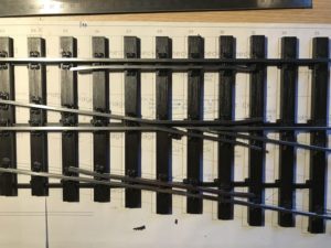
I have also now put in place the “check rails”.  These are mounted in the “check [rail] chairs” and make sure that the wheels go the correct way through the V-shaped point/switch rail construction.
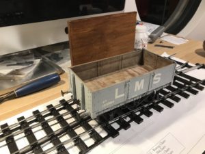


Here is one of my trucks being used to check that it runs through the wing-rails and check-rails successfully.


The “Dyak” is fully operational !!

I went to run the Impressionist model of a Stanier Mogul today at the Sydney Live Steam Locomotive Society .

.

The engine  performed very well indeed.

.

.

.

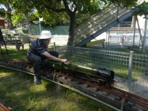
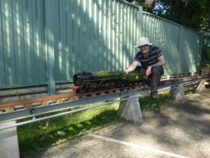
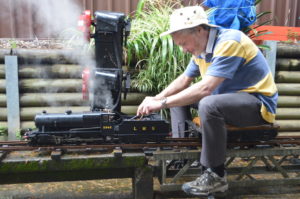
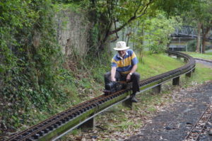
This is my “Dyak” – a freelance design which looks most like a Stanier Mogul in my view (even though the model design actaully PRE-dates the prototype by a few years! – hauling me up an incline of about 1in 60.

.

.

It was a wet day, with lots of wheelslip, but even despite this the engine performed well..

.

.

.

This was a tremendous moment for me – proof that the engne which I bought based on a comnbination of appearances and a “hunch” has proved to be a good buy.  Just as well considering it cost me $2,500 all up .


The Sydney Live Steam locomotive Society site in Ryde has a circular run of about 400m, which is superb.

See the YouTube video:   https://www.youtube.com/watch?v=-n2NSUETiIA

They let me have a go on a locomotive known to them first, I suspect to check out that I was able to follow their instructions, so some of the above video shows me running an LBSCR “Atlantic”. They then let me go solo with my “Impressionist Stanier Mogul”, and the first time around I got the whole way up their 100m long 1/60 bank, albeit with wheelslip, etc., without stopping. On a rainy day that was a mark of success apparently. Trouble is, I couldn’t repeat the feat! The loco. went very well though, and others more expert than I said that it was as “sweet” loco., and I had done very well when I bought it.
Their site has three gauges – 2½, 3½ and 5 inch gauges, interlaced and crossing over each other. Very cleverly arranged. We were using the elevated 2½ and 3½ inch tracks (these engines can only really be used to pull real passengers on elevated track) and some of the loco.s on the video are 3½ inch models.


Slaters Gauge 3 Midland Railway D299 and D351 wagons


My MR open wagons are progressing well. D299 is the side-door-only version, D351 has an end-door only – obvious from the hinge along the top end of the door.

.

.

These are the two wagons, as constructed by myself.

the upper one here is the D351.


The lower one is D299.

They haven’t been “weathered” yet, so look unrealistically clean, but that will soon be fixed.

.


I am particularly pleased with the wood-look interiors, as shown here.


Here they are, side-by-side.  

Click to enlarge, as ever.