LSWR G6 construction updated 23rd June

I often see models completed except for painting, and very nice they can look all in brass/nickel-silver.  However I suspect that doing a kit this way makes the painting/lettering/finishing more difficult.  So although I had originally thought that I would make my locomotive that way, the instructions imply that some parts (particularly the boiler) would be easier to paint during construction.

So I have now painted the boiler and smokebox.  I have also had to take all the wheels off to paint the frames (after rubbing off all the corrosion left by the soldering flux). 


I have also now fitted the brakes.  As one of my fellow-builders has had trouble with the brakes binding on the wheels, I reduced the side-to-side movement by using thin home-make washers on the outside of the frames behind the wheel bosses.


Having started the process of painting part-way through construction, I am going to carry on, particularly as I am doing the lining which will be made more difficult by lots of added details.

So here is the start of the process of painting the tanks and cab.

I made the mistake of using black metal primer on the tanks, having used light-grey primer on the boiler.  Using green paint over a different undercoat would show up as different shades of green, so I have had to re-do the green areas with grey primer!

I’m not an expert air-brush operator either, so trying to get right to the edge of colours is tricky – hence the use of masking tape to help with this.  I could touch up with a normal brush, but I’m concerned about brush marks, and the effect of the thicker paint that is inevitable if you use a brush.  For me, there is no clear answer to this, so I will just have to hope that it won’t be noticeable.  With previous models I have used “weathering’ to hide blemishes in the paintwork, but with this model I am hoping that only a small amount of “dirt and grime” will allow the attractive livery to shine through.

****

Here are a couple of pictures after I painted the majority of the areas which are going to be green (and a few areas which will later have to turn black again!).  I realise that some areas are uncertain – the front of the water tanks, for instance: green or black?  Not terribly important but the prototype picture of G6 number 257 in lined livery is taken from the side, so the fronts of the tanks and the rear of the bunker are mystery areas.


Next is to apply lining to the larger areas, and to the steps below the footplate.  My plan was to do the underneath coat in green, as shown above, then to put the white lining on, using a bow-pen and a straight edge (ruler) where possible.  I then had to hand draw the curved lines using the bow pen.  There were several hopeful thoughts here: firstly that I could draw consistent lines with the bow pen; next that the corners drawn by hand without a guide would be satisfactory; next that blemishes (and I was sure that there would be many!) could be touched up using green paint on the inside of the lines, and black on the outside; and finally that the black outside of the lining would be even although I could not possibly use an airbrush and must hope that the brushmarks will not be obvious.

So here is the result of the first attempt at the lines.


As part of this process I needed to paint the steps which hang below the footplate.  Clearly using a ruler here was not going to be possible and even the small bow-pen would be awkward around the footsteps themselves.  Nevertheless it proved to be a good trying-out ground for my scheme.


The left-hand picture (click to enlarge as ever) shows the steps and the wheel valances after my initial attempt.  The valances are OK, but the step lining is in my view too thick and uneven.

So I took my bow pen up again, loaded it with green paint and re-painted the inner edges of the lines.  I did this also for the outer edges with black paint, and managed to make the lines both thinner and with more even edges (see the RH picture).  Don’t look too closely though please: it is a long way from being perfect on close inspection.  I’m hoping, though, that on a larger model steam engine like this one, close inspection will not happen too often!

.

LSWR progress 2

I now have the radio control apparatus, seen piled on top of the superstructure .


I have opted to have sound (!) as well as battery-powered radio-control.

The battery-packs can be seen stacked on the outside edges of the side-tanks.  The speaker for the sound is in the cab at this stage.  The batteries will eventually go inside the water tanks.  So far the electrics all seem to work OK.

The kit is very well made from sheet brass (and steel).  This is so true that when parts don’t quite fit I first blame myself for not building it well enough!  So far I have had to use no molded parts, just sheet metal cut to size.  Mike Palmer, I think it is he who packs up the kits for the Gauge 3 Society, had taped parts together to aid their identification – important when several oblong bit of brass, or pieces of thin brass strip have to be identified before assembly.

I started off the kit by silver-soldering the steel frames (see the previous entry in the ‘blog), and have carried on using silver-soldering up until now – I love the way silver solder “flows” into the joints once they bare hot enough.  It’s also difficult to get the joints apart if you make a mistake though.  As you can see, progress on the body continues, and the engine is beginning to take shape.  Now that the main parts are done I’m intending to change to “soft soldering”, at a lower temperature, but I will have to se a large soldering iron, with a clean tip, as the large amounts of brass form a large “sink” for the heat.  That is, it’s difficult to get the work hot enough for the solder to melt and adhere.  I will need to use a better-cleaned tip on the iron than I am usually using.

The kit is very well thought-through, although in some ways this needs to be better explained than is done in the provided instructions.  Perhaps I’m too inexperienced at putting these models together, but it might have made things easier if I had understood a few central principles like the fact that the from part of the boiler is separate from the rest, but when it and the made-up water-tanks-and-cab section are held onto the footplate (with half-a-dozen bolts) it is all held together and in-line.

It is possible, now, to see the body mounted provisionally on the frames and wheels.  There IS something of a problem, though …

The rear wheel on the left side is missing!

I had put all the wheels in the frame, added the coupling rods and persuaded the whole assemble to turn under the power of the motor, using the radio control system and the rechargeable batteries I have bought.

After a while, though, it stopped, and on close inspection this had happened:

The mount for the crankpin had worked itself out of the black plastic molding which represents the wheel hub and spokes.  Disaster.  Can I get a new wheel from Slaters?  The trouble is that this would take weeks at best.  Can I just push the brass mount back into the wheel (and use cyano-acrylate glue)?

I suppose that whatever I do, at least I can get on with the bodywork …

LSWR G6 progress

LSWR is only one letter different from LNWR after all …

I am constructing an LSWR tank engine in Gauge 3 because basically it is the only locomotive available for this scale at a reasonable cost with the necessary attributes: a good scale representation of the original, electrical propulsion but with radio control, and a scale model of an engine which is not too large.

Fortunately, the Gauge 3 society has produced a model kit which fills these categories/criteria.  A scale model of an 0-6-0 tank engine which was used for shunting and light traffic.  Here are some pictures of the kit as I start to make the body of the lodomotive:


The frames I have started on already (see the entry “Miscellaneous, incl. Rashmi’s wedding”, but now I am starting on the main part of the engine – the boiler, water tanks cab and coal bunker.  The kit is largely in brass sheet, about half a millimeter thick.  As with the steel-sheet frames, I am trying to use silver-soldering for the major joints, thinking that later construction will be made easier if I use (lower temperature) “soft soldering”.

So far it has all gone well.

Making a switch (a point) in Gauge 3

This is serious nerd-iness, so look away ….                                [updated 15th March]

I wish to make a track upon which to run my trucks and Dyak, and whilst straight track is OK, I will also want some junctions.  Now this is an example of a British inaccurate sense of superiority and better command of language, over the New World (!).  In America, just like in the automotive world the word for what Brits call “bumpers”, they more accurately call “fenders”, and the components which Americans call “dampers” (because they damp down oscillations in the springing of car axles), the Brits call “shock absorbers” – which is not what they do at all.  In the railway world, the junction parts where a train can change tracks is called a “switch” by North Americans (accurate and descriptive) whereas I was brought up to call the same thing a “point” – what is the sense, or point, in that?

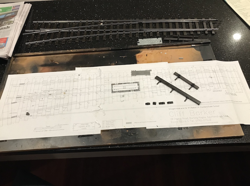
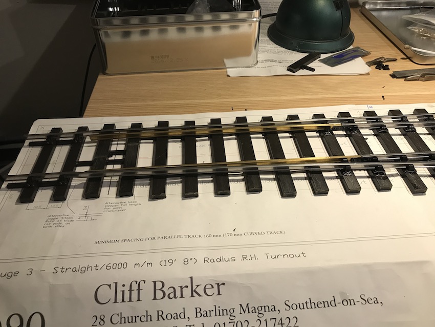
To get back to the point, I bought a kit to make the switch from a guy called Cliff Barker in England.  (sorry!)

It comprises a plan, lengths of rail, rail “chairs” (for the rail to sit in), “sleepers”, or “ties” as the americans call them, and instructions.  At the top of the picture to the right can be seen the switch as I have made one so far.

OK, OK.  I will call the switch a “turnout” as a compromise, and the ties will be “sleepers” – although why they are called this I really do not know ….

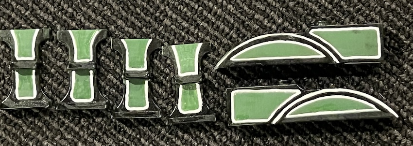
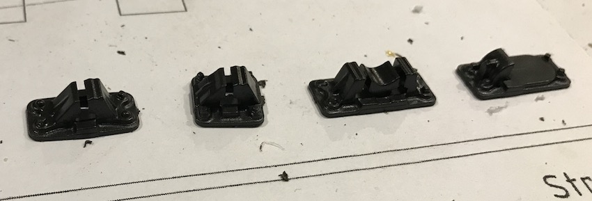
Here are some of the rail chairs.  
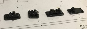
Left-to-right are standard rail-chair, and narrower one for tightly-spaced rails (called a “bridge chair” for some obscure reason), and double chair for the check rails (see later), and a slide chair (ditto).

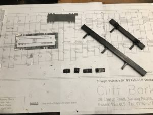
This is a closer view of the plan and the parts.

The instructions suggest that the turnout is largely built using the plan as a definitive guide to positioning the parts, but using my experience for ScaleSeven, I disagree, as will become evident later.

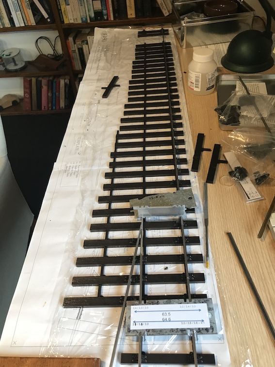
There is also a rail gauge – a device which sets the correct width between the tracks. – you can see two in the picture: the nicely made one from Cliff Barker, and the cruder one cut from a flat piece of steel by myself – with paper stuck to it to show what the actual dimensions are.  Not always quite what they are supposed to be!

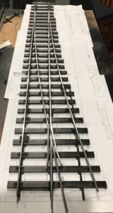
Here is the first one I built: a 4,500mm curved “turnout”.  I’m now onto doing a 6000mm one.

The instructions from CB suggest building the turnout mainly relying on the printed plan.  A problem with that is that this does not guarantee that the distance between the rails is accurate.  In straight track the distance between the inside edges of the two rails should be 63.5mm (exactly 4 foot eight-and-a-half inches or Standard Gauge, scaled down).  On curved track this has to be widened slightly to stop grinding of the wheels on corners.  Up to 64.5mm on curved track.

In turnout construction/pointwork this is crucial.

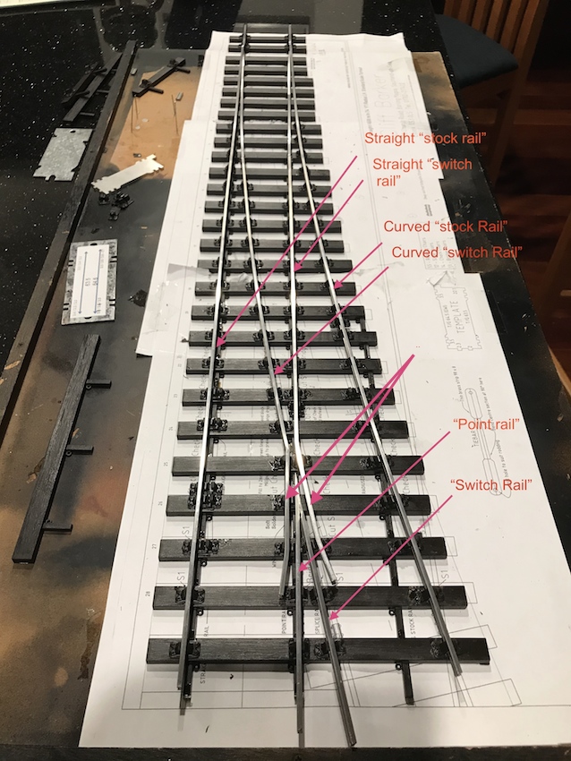
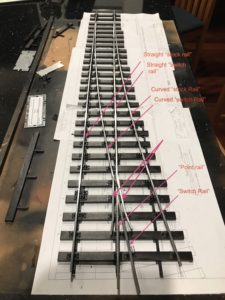
It is also difficult to follow the nomenclature of the turnout’s various bits of rail: see the diagram.  Click to enlarge.

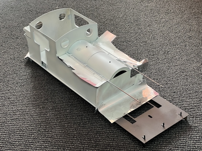
IMO the best way to construct a turnout and get the gauges correct is to glue the straight “stock rail” down first.  The ties are plastic, and methyl-ethyl ketone (“MEK”, or plumbers welding compound) is used to weld the railchairs to the tie-bars/sleepers.


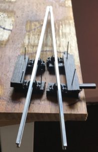
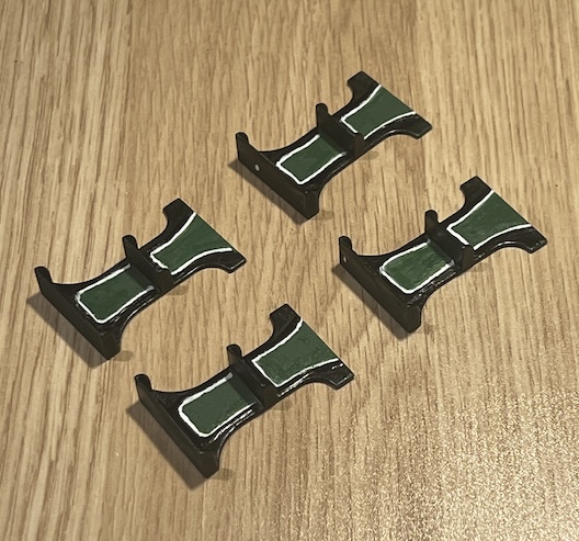
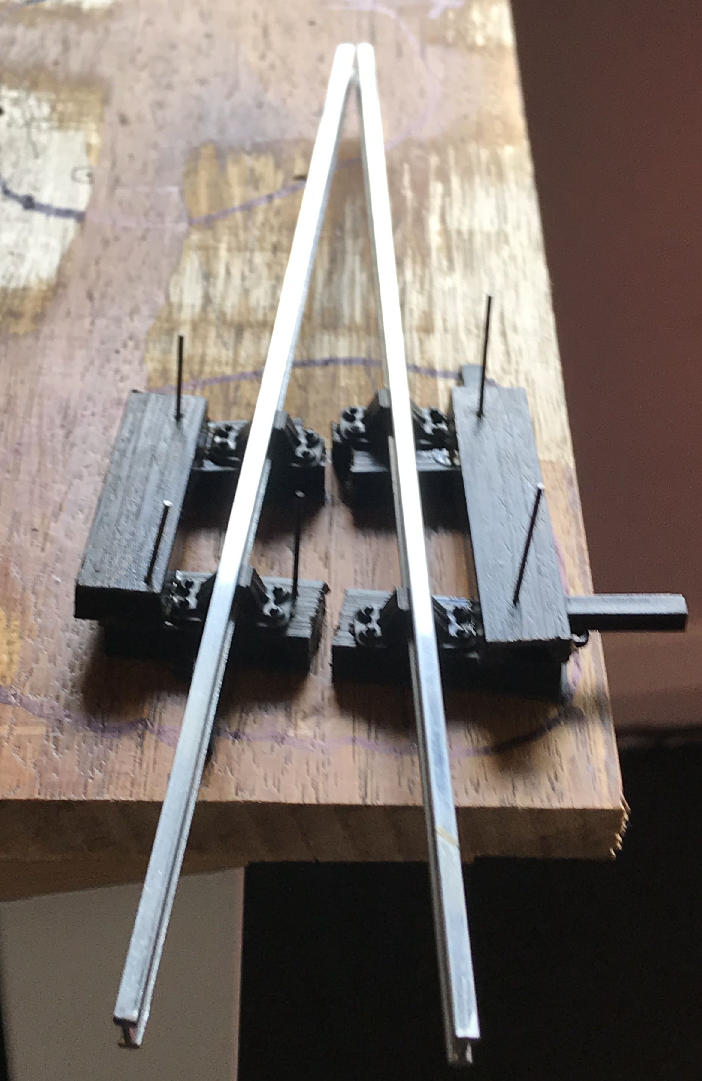
It is then necessary to weld/silver-solder/soft solder the point rail and the switch rail together, at the correct angle (tricky). On the left is the “jig” I have made to help with this: four rail-chairs are used to hold the rail (at the correct inclination).  The chairs are stuck onto offcuts of sleepers/ties and arranged on a flat piece of wood at the correct angle for the switch.  The rails are bent and filed to the correct profile then silver-soldered (it could be soft-soldered, but the silver-soldering will be stronger).

When I made the first turnout I followed instructions to position and stick down the curved stock rail after the straight one, fitting the switch/point V-constuction in between.  The problem with this approach is that acheiving the corrrect rail gauges (including gauge-widening for the curved rails) is very difficult.  In fact I had to take some of the railchairs off the sleepers to adjust their position – very difficult as they had been “welded” together!  Constructing it progressively from the straight to the curved side makes setting the rail-to-rail widths easier, I believe.

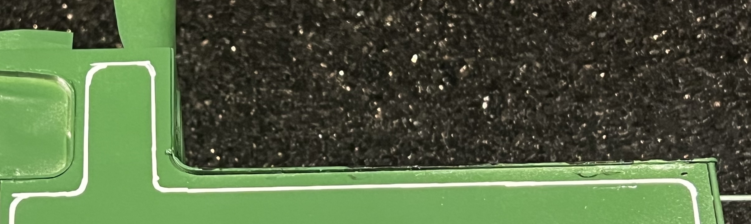
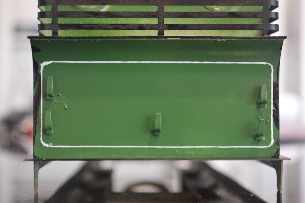
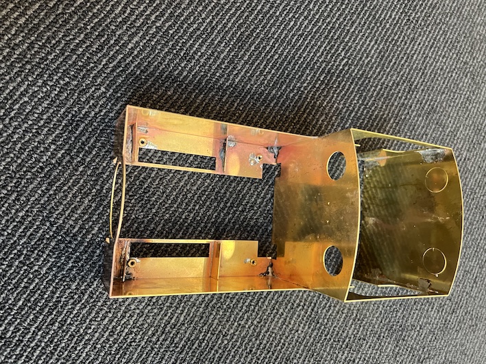
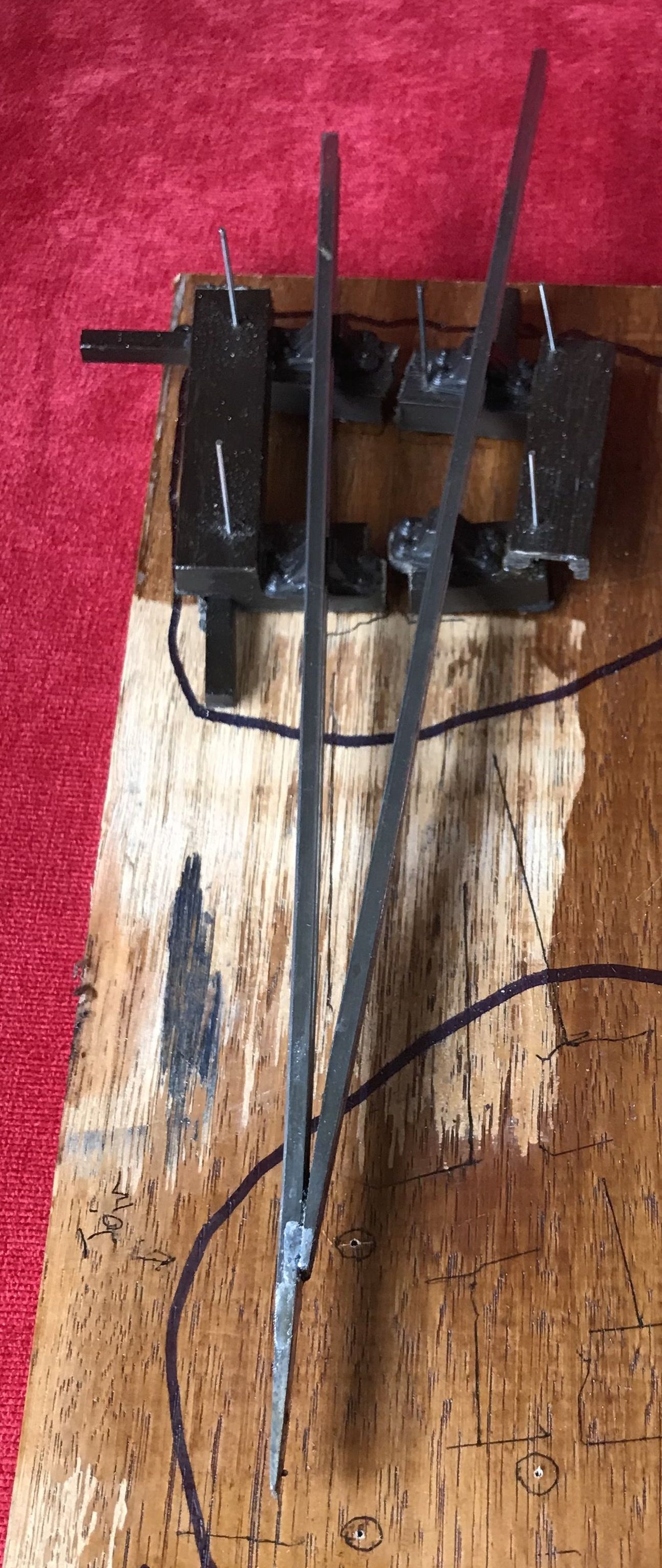
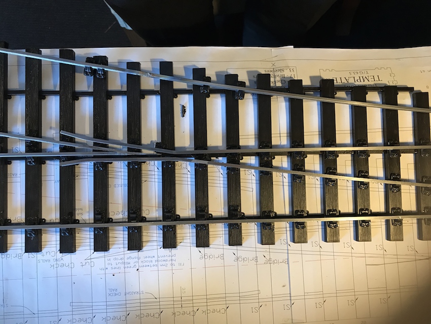
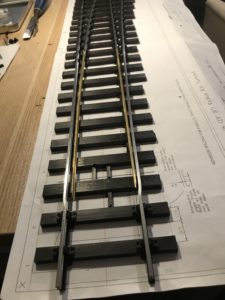
Before one starts sticking the rails down, however, it ts wise to shape/file/machine the “stock” rails – the long ones on the outsides of the switch – to allow the point blades to direct the wheels smoothly one way or the other – see the picture, taken from later in the construction, but which shows how I chose to make “joggles” (as Cliff Barker calls them) to allow for the point blades effectively to be recessed into the running rails. By bending the rails outward about 10-15 degrees, then at a short distance further along (CB suggests just 8mm) bending the rail back into line, the minor bend is made which accommodates the point blade.

An alternative is to file recesses into the running rail, but this is more difficult.  It is good to remember to make mirror-image “joggles”.  I did not, but as I was making two or more turnouts it didn’t really matter!  Clear thinking before sticking the straight stock rail down to the sleepers/ties is needed, but this is the first thing to do.  The printed plan is useful to space out the sleepers at this stage.

So position the V-shaped point/switch rail construction at the correct gauge from the straight stock rail and the correct position along the whole plan, with regard to where the curved stock rail will be.  It is helpful to shape the curved stock rail approxiately beforehand to allow the positioning of the V-shaped point/switch rail construction.

In my experience it is best to position the straight stock-rail to V-construction at the correct gauge first.  Put simply, I construct starting at the straight stock rail and then work towards the curved side, using the plan as a rough guide only (especially useful for bending the curved switch rail). 

Next are the curved, then the straight switch rails.  Both “switch rails” need to be bent to include the “wing rails” which go on either side of the V-shaped construction. 

The “switch blades” are machined rails narrowed down to provide the narrow blades redirecting the wheels straight on or into the “turnout”

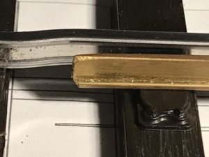
To the left is the picture showing the “joggles”. 

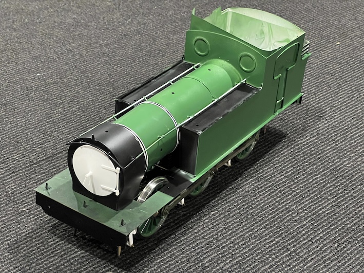
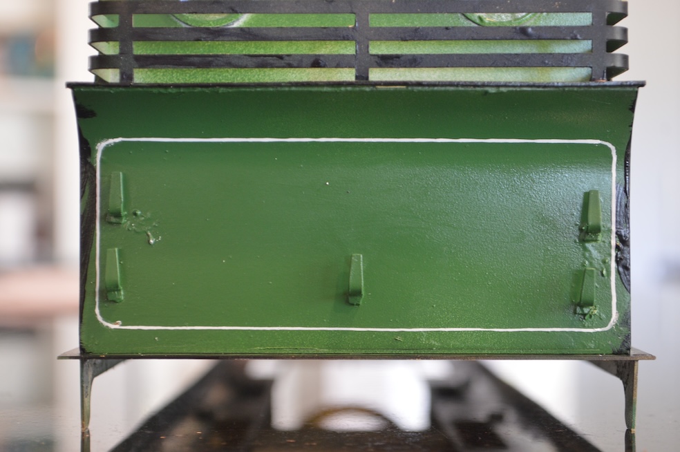
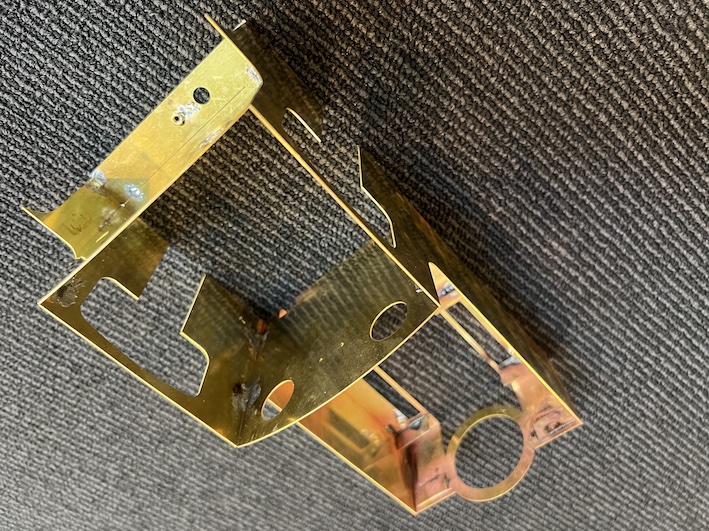
The switch blades are joined onto the switch rails in my turnouts using a plastic connector which looks like a real fishplate but here is acting as a hinge point. In the picture below, about 9 sleepers up the switch blades from the sharp end can be seen the joint to the switch rails.

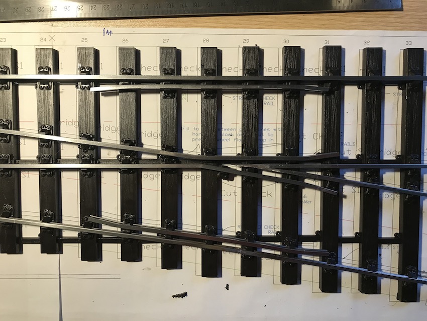
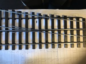
Now the running rails are now all in place, but as can be seen if you inspect closely, the chairs aren’t in place to support the switch blades,  These supports need to allow lateral movement of the switch rails, and so are the “slide chairs”, which allow this lateral movement whilst supporting the weight of the rail (and locomotive) when necessary.  One such slide chair can be seen under the tip of the switch blade above.

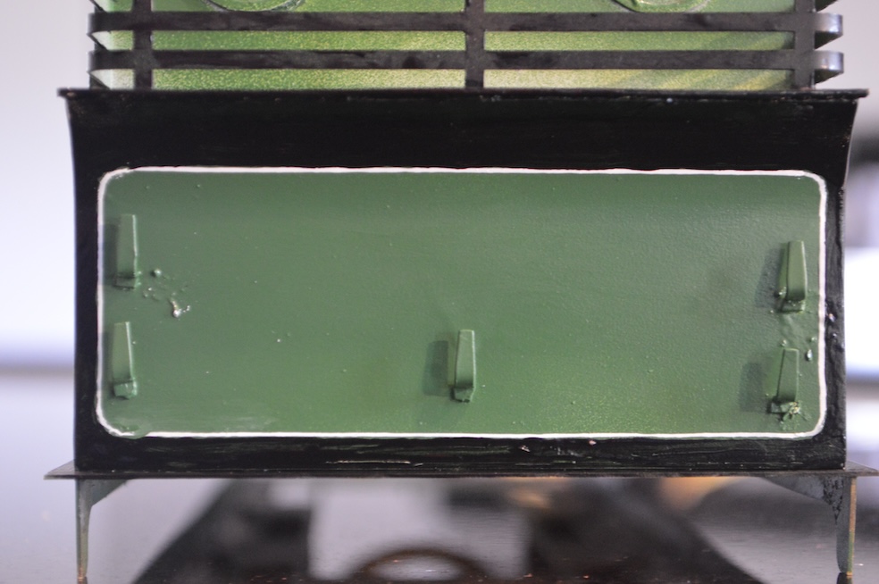
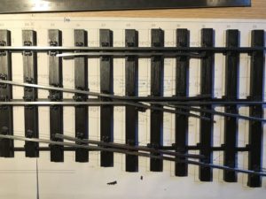
I have also now put in place the “check rails”.  These are mounted in the “check [rail] chairs” and make sure that the wheels go the correct way through the V-shaped point/switch rail construction.


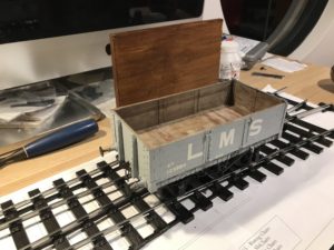
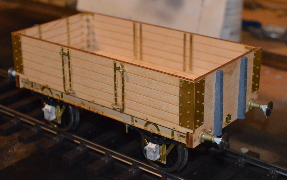
Here is one of my trucks being used to check that it runs through the wing-rails and check-rails successfully.


Slaters Gauge 3 Midland Railway D299 wagon – 2

“Slaters Gauge 3 Midland Railway D299 wagon – 2” because I have shown a little bit of the construction of this kit from Slaters Plastikard in my entry “Gauge 3 action” earlier.

Despite name of the company who made it, this kit has almost no plastic!  It is nearly all wood and metal, which I greatly like.  It is also phenomenally well-designed and made, and all fits together very precisely and accurately. My previous entry left it at the stage where the body had been put together, but then I had the opportunity of having help with my “live steam” Dyak, and so the wagon project was abandoned.  

Well here I am back at the wagon works.

After the wonder of putting together the beautifully laser-cut wooden body, and the tedium of inserting over a hundred dummy bolts (about 1x5mm each!), I have put on the wheels, including the suspension, and the rest of the underframe details.

As you can see from this and the previous picture, these wagons often only had brakes on one side, and that is what I am modelling.

Painting should be straightforward – in theory, if not in practice!  Everything above the bottom of the sole bar in wagon grey, and everything below in black!  What is more, wagon grey was variable in shade, so almost any light- (or indeed quite dark-) grey is realistic!

I found a grey. primer, but once applied, I have decided it is a bit dark to look nice (I want to have a variable grey fleet of wagons, even if I cannot have a colourful collection).  So I will apply a lighter coat of grey later – I had hoped that the primer would double as a final colour.

In any case the primer came from a “rattle can”, and didn’t provide an even coat, not getting into the corners well at all.  Using the airbrushes with a lighter grey should fix that issue as well as making the colour more acceptable (to me …).  On the other hand the primer appears to have covered all the metalwork, which is what I really needed it to do.

Back to the Gauge 3 Woodbury wagon

Back to the Gauge 3 Woodbury wagon, a model of the Midland Railway diagram D302 5-plank “open wagon”.

I have now put the (initial) topcoat on – a representation of Midland Railway wagon grey, with black underframe gear.  Although it is gong to be a later era wagon (London Midland and Scottish Railway years), I am putting some Midland Railway lettering on it.  My intention is then to paint over it, “weather” it, and finish it in LMS colours and script.

So here it is with MR insignia, some weathering, and with the inside painted to resemble wood.  This being Gauge 3, the transfers (“decals”)a re difficult to apply over the lumpy details on the sides without either of both of cracks in the transfers and “tenting” of the transfers over the raised detail molding.

It might be better if I could paint the lettering on, but I am simply not capable of that!  On the second view it is possible to see where I am preparing to paint a replaced plank – in unpainted wood finish.


More of “Another Wagon”

-This other wagon is a model of a Railway Clearing House (“RCH”) design from 1923, the model produced as I’ve previously said, by Mike Williams.


I have now put most of the underframe together, as this shows: the brake gear is on, and the springs, etc.


The details go together quite well, and although I have had a little more trouble than with more expensive kits, by the time this is done I think it will look fine, and it is only about 60% of the price!

For instance the brake gear,  instead of being made of individual components (as in more elaborate (and expensive) kits, is a single resin moulding.  The brakes on this moulding did not line up properly with the wheels so I had to saw the moulding in two, then fit it to the underframe.  It will look fine once painted, so this really isn’t a major problem.


I’ve now had a chance to put on the “primer”, and as this is black, it will do well as the final colour also, I’m hoping ….

This actually shows one of the ways in which this kit has been “a little more trouble”: given that there is no floor, there was nowhere to fix the brake safety straps to, so I had to add the strips of balsa wood which you can see.  Not a major problem either, of course.

Gauge 3

It’s arrived!

This is a Gauge 3 locomotive to run in the garden, if I can get it going.

It is actually not a model of any particular locomotive, but it’s main merit is that it is a “live steam” and coal-fired model.

The problem, from my point of view, is that I don’t know how to run it: I cannot light a fire in its firebox, I don’t know how to keep the boiler full of water, I don’t know how to keep it going at all. Even more alarming, I don’t even know that it will work at all!

From what I can tell, this model was probably built in the 1930s or 1049s, but I don’t know by whom. I bought it from “Station Road Steam” in Lincolnshire, and as far as I know there is no history coming with it. It looks well-made, and looks as though it should work OK. It is apparently built to a high standard (according to Station Road Steam), but they didn’t test it and offer no guarantees. Having looked around for a while, though, it looked as good a prospect as any that I have seen advertised for sale recently. From appearances, it has never actually run on a track, although it looks as though it has had a fire in the firebox. Perhaps whoever built it just lost interest once he had proved that he could do it (build a live steam model). Sadly I don’t suppose that I will ever find out its history.


I just hope that I don’t cause an explosion the first time I try to fire up the boiler.

I look upon it as being an impressionist model of an LMS Stanier Mogul, and if I can get it going, I will then paint it accordingly.

The aftermath

Further to the previous ‘blog, here are some more pictures as the track is lifted from my railway.

The track has been lifted copy

The trackbed on the gradient out of the colliery.

Trackbed without track copyNo more Garratt climbing the bank, no more 8F pulling the coal wagons.

The trackbed almost looks like a real one after the tracks are gone.

The track has been lifted 2 copy


This picture is less real ….


No railway left copy


So here is the final view.

The new owners might want to use the baseboards (unlikely) or use it as shelving.  Or, most likely, knock it all down.  I just couldn’t bring myself to do it ….

The lights go out copy


… and the lights go out for the last time.

A sad day ….

After 20 years of construction, this is the time of deconstruction ….

My model railway at Mount Riverview has to be taken apart.

IMG_1397


This is after the wagons have been packed away and the buildings removed.


IMG_1400


Now the deforestation has occurred.

IMG_1401


Now the tracks are being torn up ….


I spent the day at our old house, in the cellar pulling apart the model railway.  It was bit sad.  Odd, also, remembering the struggles to get this point working, that bit of scenery to look right, etc.

Overall my verdict is that I did a good job, but I certainly wouldn’t do it the same way ever again, or advise anyone to do the same thing.  I copied what Dad had done in Liverpool (UK), rather than using modern techniques, ideas and modelling gear.  It would have been so much easier if I had done it differently.  Sometimes you simply shouldn’t repeat the experiences of the past.

If (and it’s not certain) I build another model daily, what will I do?  Another Scale 7 model, but portable, smaller and linear (rather than circular)?  Gauge 3 (in the garden possibly)?  S7 in the garden?  If I go to G3, or decide not to build another railway, what should I do with the stuff which I have now?

So many questions, no answers.