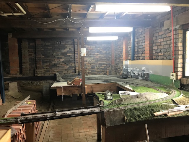
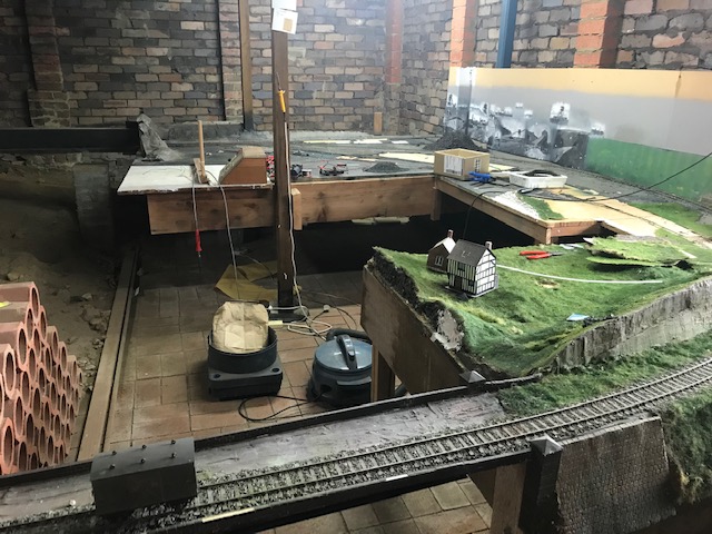
After 20 years of construction, this is the time of deconstruction ….
My model railway at Mount Riverview has to be taken apart.
This is after the wagons have been packed away and the buildings removed.
Now the deforestation has occurred.
Now the tracks are being torn up ….
I spent the day at our old house, in the cellar pulling apart the model railway. It was bit sad. Odd, also, remembering the struggles to get this point working, that bit of scenery to look right, etc.
Overall my verdict is that I did a good job, but I certainly wouldn’t do it the same way ever again, or advise anyone to do the same thing. I copied what Dad had done in Liverpool (UK), rather than using modern techniques, ideas and modelling gear. It would have been so much easier if I had done it differently. Sometimes you simply shouldn’t repeat the experiences of the past.
If (and it’s not certain) I build another model daily, what will I do? Another Scale 7 model, but portable, smaller and linear (rather than circular)? Gauge 3 (in the garden possibly)? S7 in the garden? If I go to G3, or decide not to build another railway, what should I do with the stuff which I have now?
To those in the know, the title is the sign when map reading that a railway track used to be there.
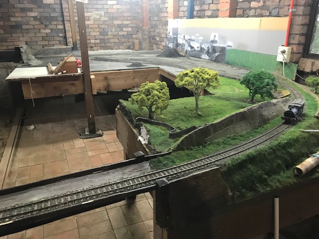
Well, my model railway hasn’t gone, yet, but it soon will have.
It’s a bit sad for me actually – it has taken 20+ years to get to this state, and soon I will have to dismantle all this.
I have started by removing all the frames carrying plastic sheets which stopped the bat-poo spoiling my scenery. This has given me a chance to take some final pictures (possible final – see later) without the plastic sheeting getting in the way.
Click to enlarge, as ever.
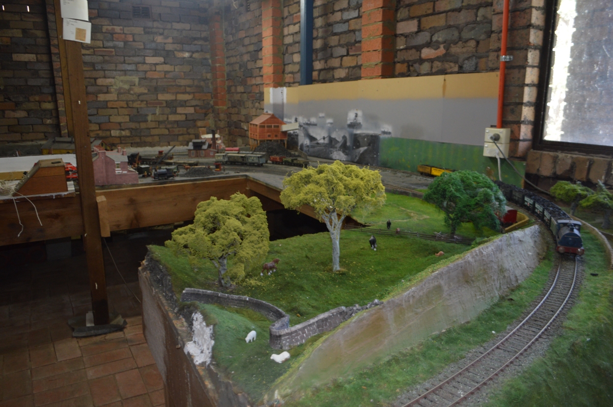
Here is an overall view.
The Peckett 0-4-0ST is climbing the bank towards the photographer, past the farmer’s fields complete with sheep and horses (and kangaroo if you look closely).
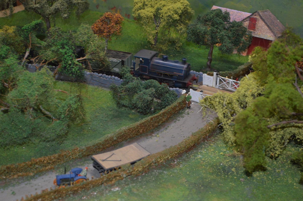
Here is a view of the countryside section, with the train going over a level crossing.
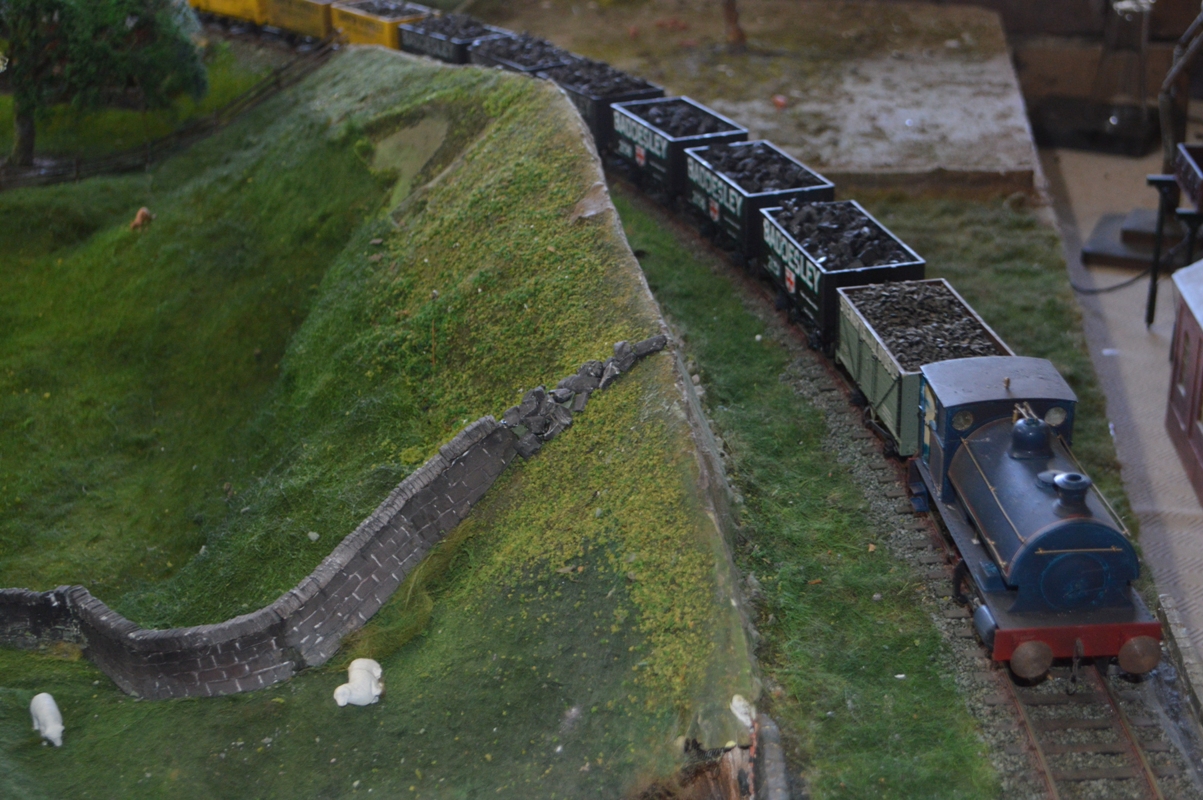
Here is the Peckett at the top of the hill.
The trouble with these pictures you may already have noticed – I took them on the spur of a moment, just after taking off the bat-poo protectors, and so they aren’t carefully set up. Obvious detractors – the sheep on its side in the last photo., the “lonely” wagon off the rails in the middle of the coalyard in the first picture [and picture 2], the drawbar for the trailer on the road, not connected to the tractor but instead ON the trailer, in picture 3!
So maybe I will have to take some better pictures, with better locomotives, as well – my Garratt, my L&Y “pug” or my Stanier 8F !
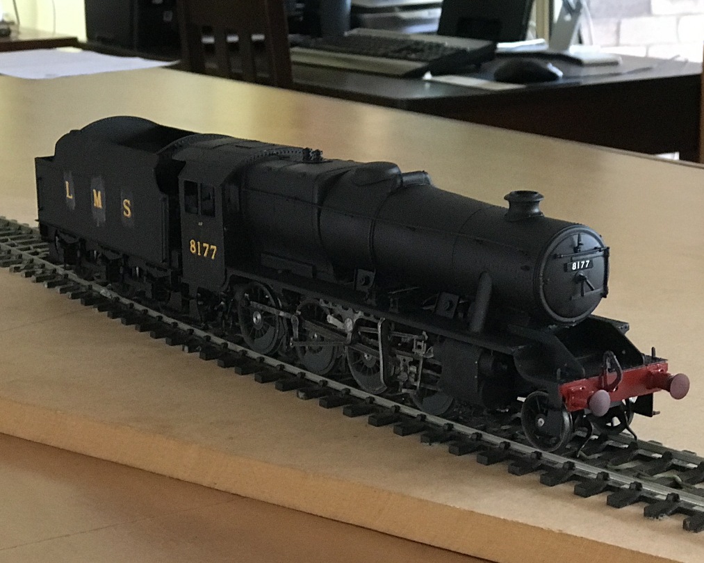
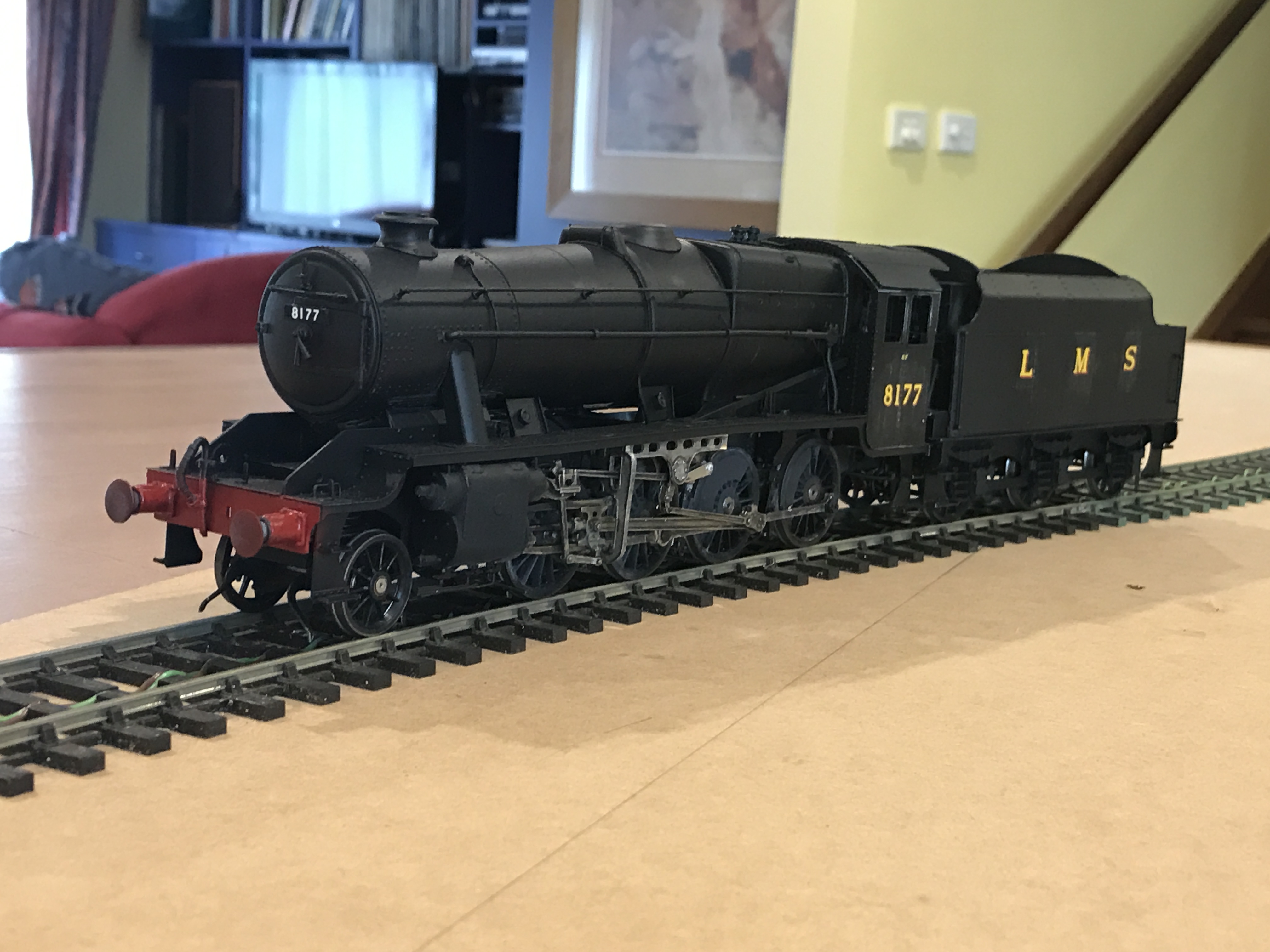
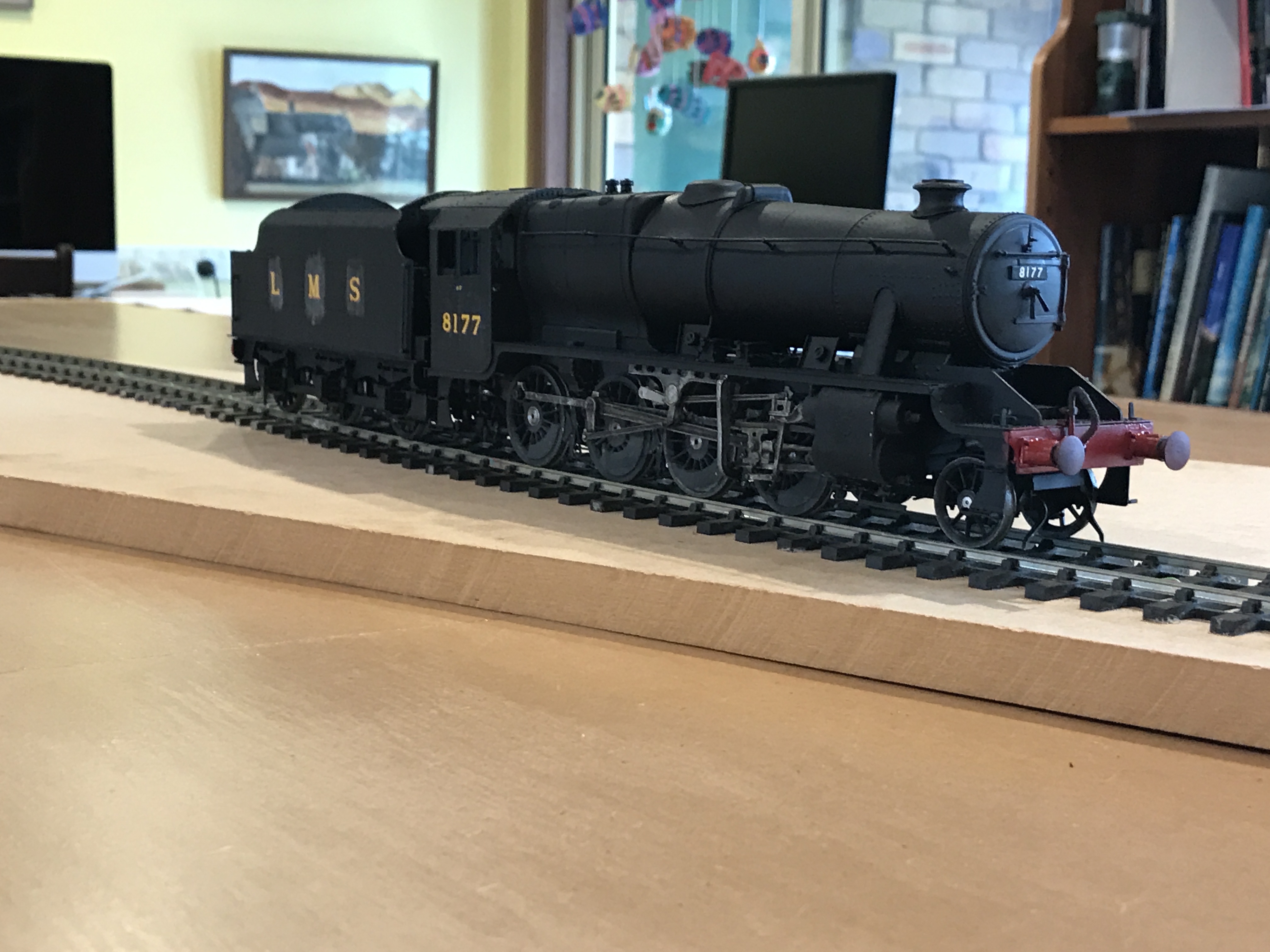
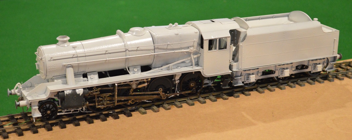
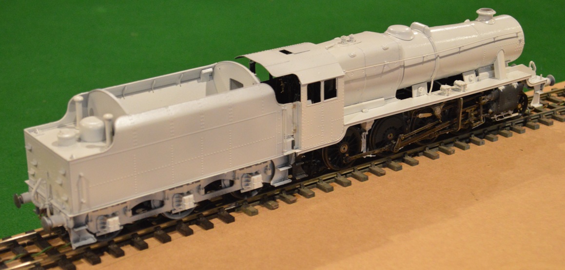
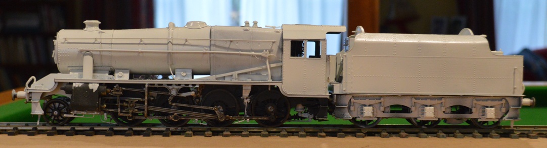
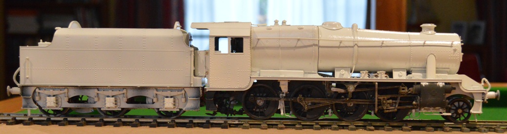
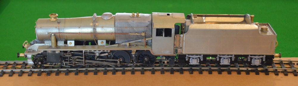
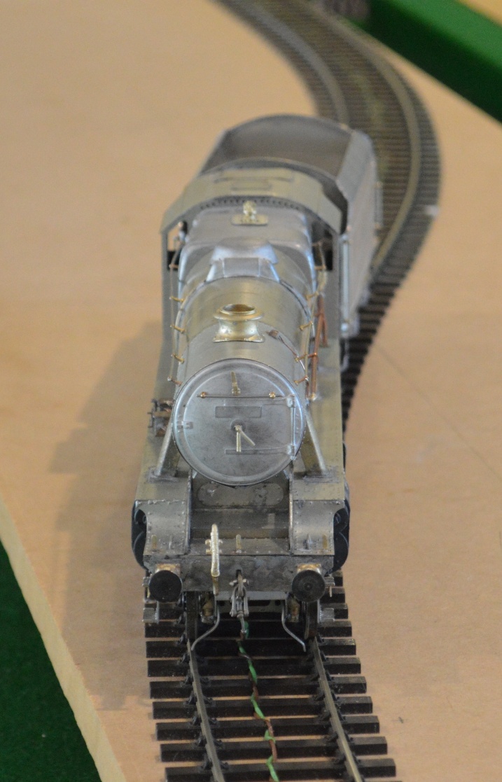
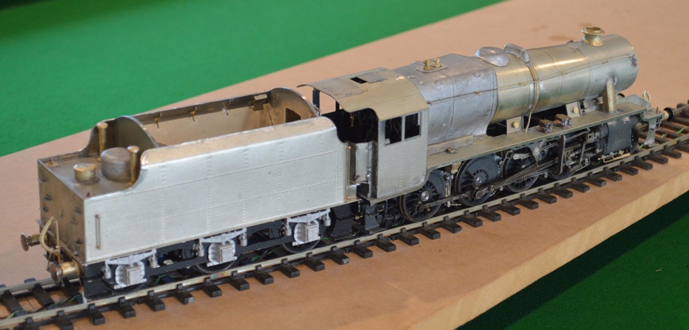
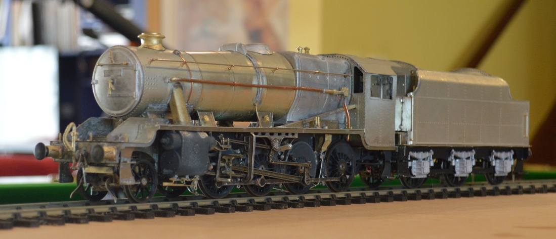
It has taken a long time, and I have had to re-lay some of the track, but I can finally show the model Stanier 8F locomotive pulling a fairly long train of coal wagon around my model of a colliery.
This shows my 7mm scale, Scale-Seven, model of a Stanier 8F 2-8-0 freight locomotive running around my model colliery. The track is a bit rough, and I had to relay some of it to allow the eight-coupled (long fixed wheelbase) locomotive to go around the curves, and up and down the gradients I have made in the model.
In fact at the moment, I can make the engine and wagons go around the loop in an anti-clockwise direction, but if I try to have it run around clockwise, it comes off the rails!
However I suspect that the problem is with the track work, rather than the engine which I made.
I realise that the model railway which I have built in our cellar is almost entirely only for my own amusement and satisfaction. I had originally aimed that our two sons would develop an interest in models, railways in particular (though I also tried cars, boats and a hovercraft). They being Australian boys, though, their interests turned to outdoor games. Actually, in the long term this is almost certainly much better of course: both Andrew and Nick still play hockey/cricket/football. On the other hand, the only other person whom I know to be an interested reader about my models is brother John, so this page is dedicated to him. John has been kind enough to appear enthusiastic about my achievements, and although he only actually sees my railway once every few years (when he visits Australia), he has maintained an interest. A modeller-by-proxy, perhaps?
Mark outlined on his page the origins of the family interest in railways, and I will write a little about model railways. When Mark and I were small, our Dad bought us railway engines for “00” gauge, and I can remember installing a floor in our attic of the house in Woolton, Liverpool, which was largely done so that we could have an “00”-gauge railway up there. Such a railway was built, and we spent many hours up there subsequently. There were echos of this thirty years later when I paved our cellar in Mount Riverview NSW for very similar reasons. Mark (and Dad, I think) were mostly interested in simply seeing the trains run around, with lovely rolling stock (engines, wagons and coaches), timetables and operating schedules. I, however, was always more interested in the details of the models and the scenery/surroundings. I was later bought a smaller scale as my own railway in 3mm-to-the-foot or “TT” scale. John was later started in 2mm or “N” scale.
My interest in detailed model construction led to the construction of model locomotives in “00” scale/gauge, but this proved conceptually unsatisfactory because for obscure commercial reasons the manufacturers of ready-to-run models had created this anomaly: 4mm scale on 16.5mm track: the wrong scale:gauge combination – in 4mm the gauge should be 18.95mm. Originally the 16.5mm gauge track was made for “H0” scale (3.5mm), which is correct. “H0” in half “0-gauge”, you see. I hated the idea of spending hours making a model when I knew that the gauge would be all wrong …
That, combined with the greater detail available in 7mm scale led me to want to build in 0-gauge. Moving to Australia, and having two boys as children, gave me the excuse to get going. So I paved the cellar, and set off in 7mm scale, 32mm gauge. I laid a 4m circle of track on shelves in the cellar. My protestations that my 0-gauge railway was built for the small boys’ benefit was rather undermined by Sue seeing the sticker on the outside of one of the model kits, saying “This is a scale model, not suitable for children under the age of 14” !!! Anyway, I persisted, but has any reader noticed the problem? It took me a rather embarrassing length of time to realise, but the scale:gauge combination is still wrong and the gauge should be 33mm !!!!
33mm gauge/7mm scale is called ScaleSeven. I joined the Scale Seven Society (membership about 300 people, worldwide), took up all of the 32mm gauge circuit and rebuilt it in 33mm gauge, then re-gauged three locomotives and about half-a-dozen wagons. I deny being at all autistic, just seriously obsessive, and it had to be right. These video pictures are of the model railway which I have built since.
Here is a sequence showing the locomotive going through the coalyard of my model colliery. The train is going unrealistically fast in scale speed, of course.
I have just added three more coal trucks to the fleet, and had an interesting experience yesterday as I tried to have the train to twelve coal trucks pulled around the circuit by my model Peckett 0-4-0 saddle tank (actually originally built by my father and John, for Nick, since repainted by me. My layout has a hill on it (not all railways are perfectly flat …..) and the Peckett could not pull the train up the hill:
As you see, wheelslip occurred and the train ground to a halt. Clearly a more powerful locomotive was required. As several real colliery owners did in the UK in the 20th century, I turned to a Garratt articulated locomotive:
My model Garratt has two motors, just like the original articulated locomotives did, and the greater power available means that the gradient was easily conquered.
There is a scenic section on my model railway, also, and the final video shows this:
It may not be to everyone’s taste or interest, but my ‘blog about building this kit has entertained me and John, at least! It is very much the same as some entries which I have made on the Western Thunder website <http://box5457.temp.domains/~coulshed/australian-family-events/>, but that one is for seriously train-autistic people (joke ……..)
Even at this stage there are mistakes to be made, and lessons to learn, perhaps.
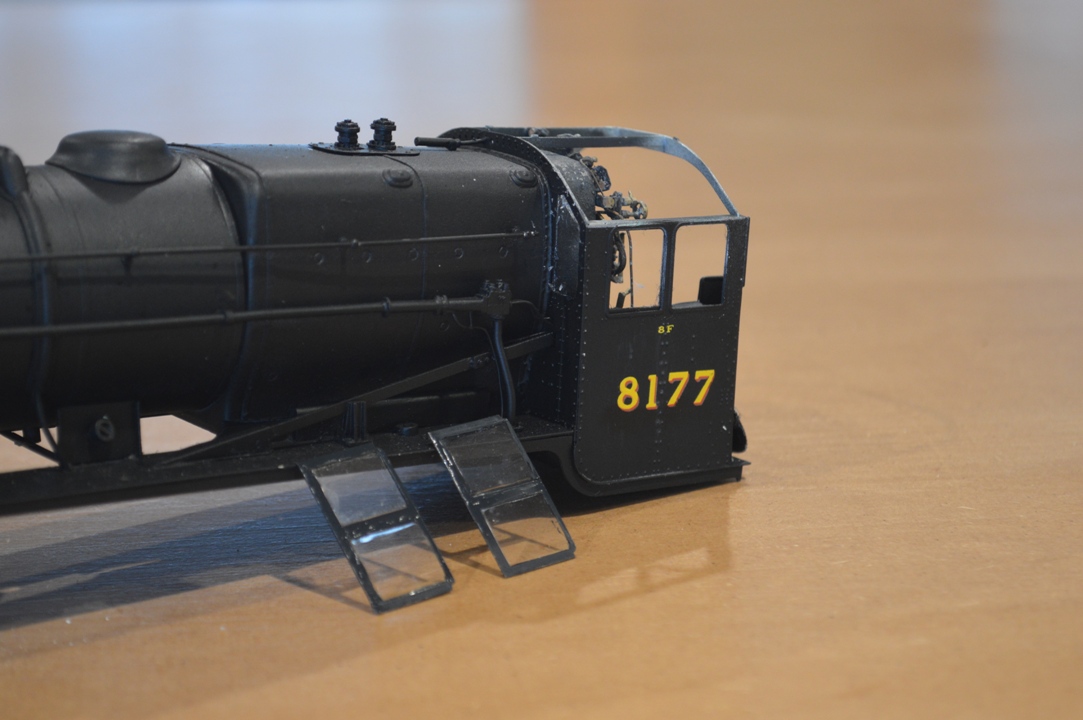
For those who see these things there are several problems with the locomotive as seen here.
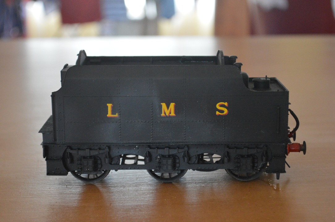
Most obvious is the water-based varnish covering the letters and numbers. Perhaps less obvious is the lack of window-glass. Least obvious (perhaps) is the fact that the central two pairs of driving wheels in the second picture are not exactly on the rails ….
In order.
I have had trouble with solvent-based varnish destroying transfers in the past, so once my transfers were in place I fixed them with water-based matt varnish, with the results shown in the pictures. This in itself I did not see as too much of a problem, because I thought that once an airbrush-applied coat was put on, the streaking would vanish.
My mistake, though, was to use a short-cut and (thinking that the varnish already there would protect the transfers) I used a “Testors” aerosol “Dullcote” varnish on the tender sides. Whilst the transfers survived, it produced bubbles and wrinkles in some of the plain paintwork!
Disaster. They were large enough patches that, even allowing for my intention to produce a weathered appearance, I couldn’t leave them as they were. I didn’t want to have to do the whole sides all over again, so rubbed off the sections of affected paintwork with a glass fibre brush, back to bare metal, then resprayed with primer, masking the letterwork.
Then I resprayed with matt black.
It isn’t perfect by any means, but after weathering I don’t think the differences will be visible.
Next the windows.
Initially I wanted to use microscope coverslips to make real glass windows, and even bought a tungsten scriber to cut the glass. However I soon realised that the coverslips were incredibly fragile, and I thought that in my hands would soon be broken in place on the loco., when replacement would be very difficult. Also I realised that there was no way to produce the front-facing windows on the cab from glass, anyway. Whatever method I used, I realised that the front windows were going to be impossible to position without taking the cab roof off. So rip it off I had to do (well, carefully unsolder and lift it off ….).
Using plastic “glass” was OK until I was unwise/uneducated enough to use cyanoacrylate to glue the side window frames in place. Araldite had been fine to secure the plastic sheet to the frames, but cyanoacrylate has made some of the glass go “misty”. Well, I suppose there may have been quite a bit of steam in the cab at times ….
Finally the problem with the wheels.
Once again, this is probably something a more experience model-builder would have avoided, but bear in mind that this is the first tender engine kit that I have ever made – three tank engines and a Garratt before this.
This illustrates the problem, and my solution (so far – I haven’t fully tested it yet!
The MOK kit comes with a drawbar which has a disc at one end and an elongated disc at the other (running-track shaped). Naively, I went for the close-coupled length.
It looks good, and would work well on straight track, but on curves the tender will not articulate enough with the locomotive, and one or other comes off the track. The problem was that I had cut off the extra length of the elongated end of the drawbar. So I have had to reconstruct it from flat brass strip and solder it onto the drawbar, as shown. With a slot at the tender end, I’m hoping that the tender can look realistically close to the engine itself when pushed together, but will move apart enough to go around 2m radius curves when in forward motion. We will see eventually if this works!
Incidentally, those who have followed this thread may notice something has changed in the pictures. Nick and Andrew were worried that me using their pool table for pictures might end up in damage to the green baize, and so we have now constructed a wooden top for the table! We had time for this because of our recent weather – Australia really is a different world of weather, or is it global warming? It is still warm, but we’ve had over 150mm of rain in the 5 days, and so plenty of time for making things like table-covers – and model locomotives, of course!
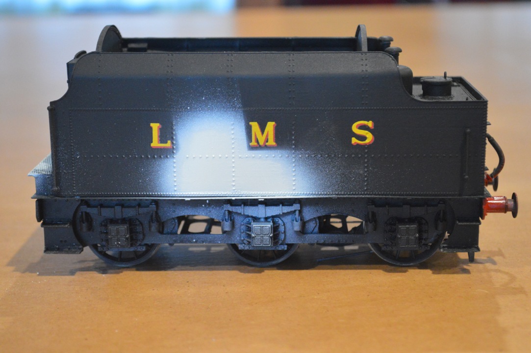
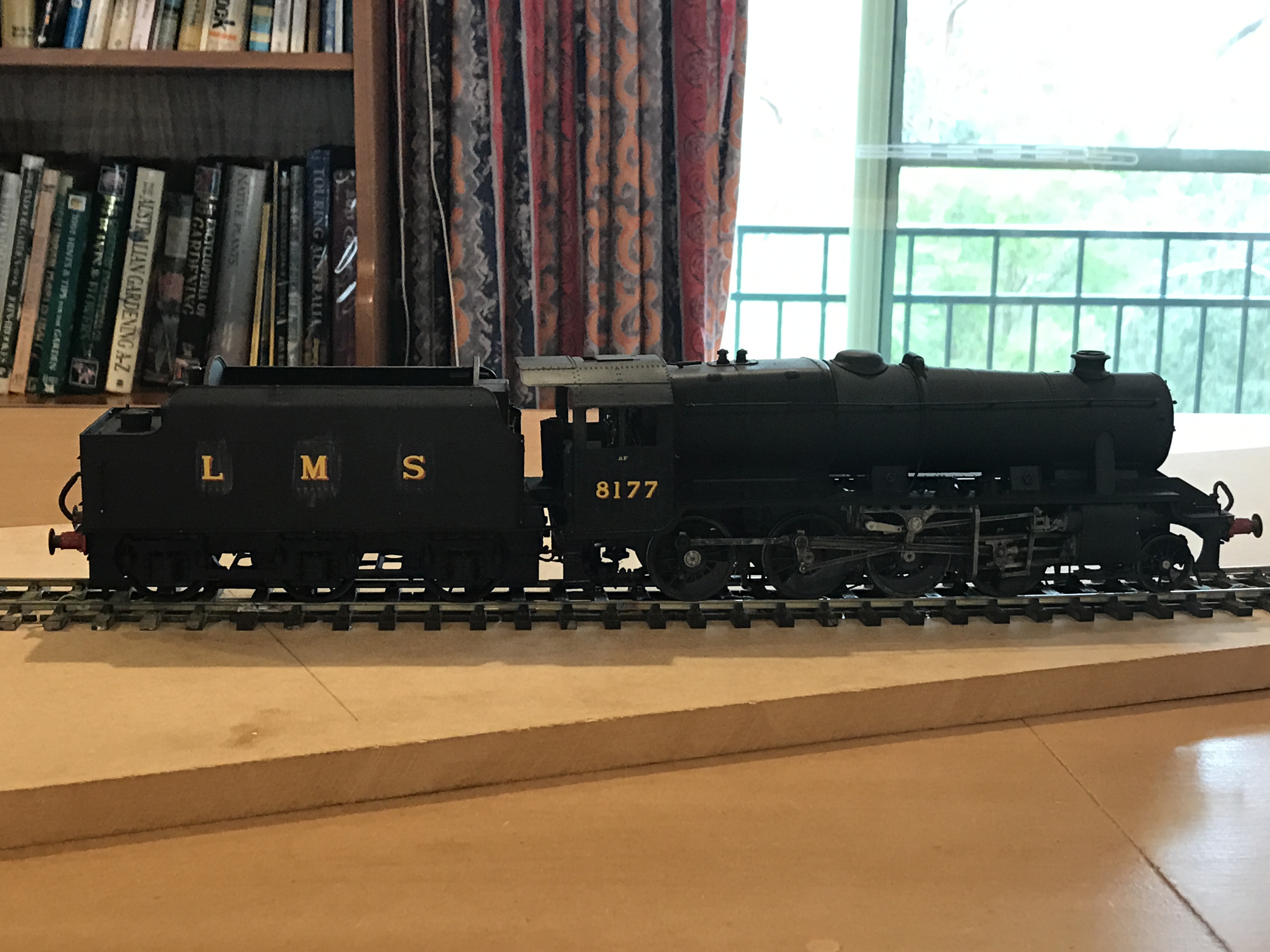
It still has some way to go, but the locomotive is looking more like the real thing since I added number and letters to the painting.
I chose number 8177 because there is a nice photo. of this particular engine on the Settle and Carlisle railway in LMS days.
I have put the transfers on and then sealed them on using water-soluble matt varnish.
Unfortunately, as can be seen, this leaves a visible stain.
However application of a spray-on coat of mgt varnish will remove this I think.
I have taken some videos of the locomotive moving on my test track, which I will add once they have uploaded onto YouTube (this takes literally hours!).
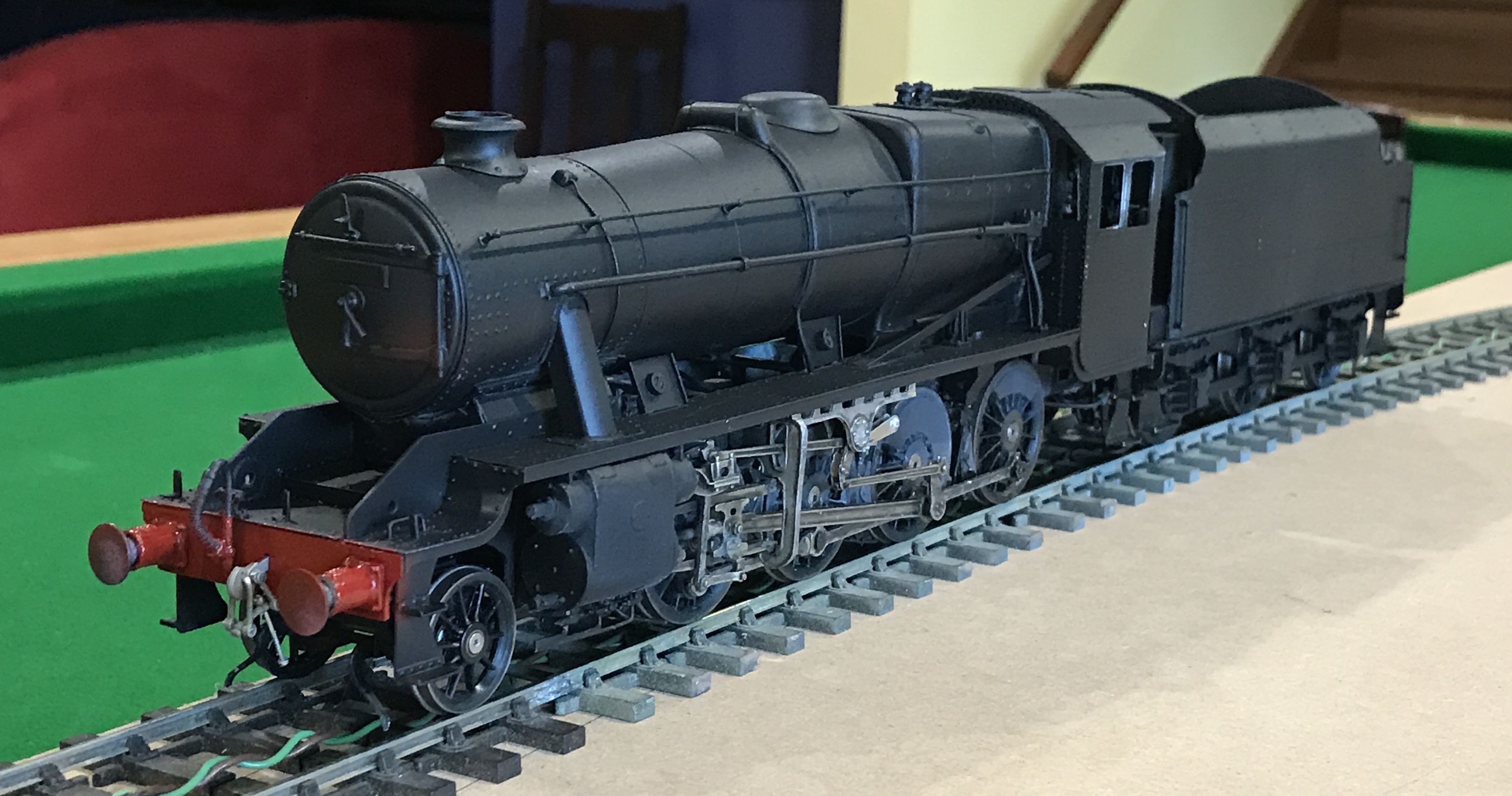
I still have to add the cab windows, colour the coupling hooks black and then make the engine appear more realistic with weathering.
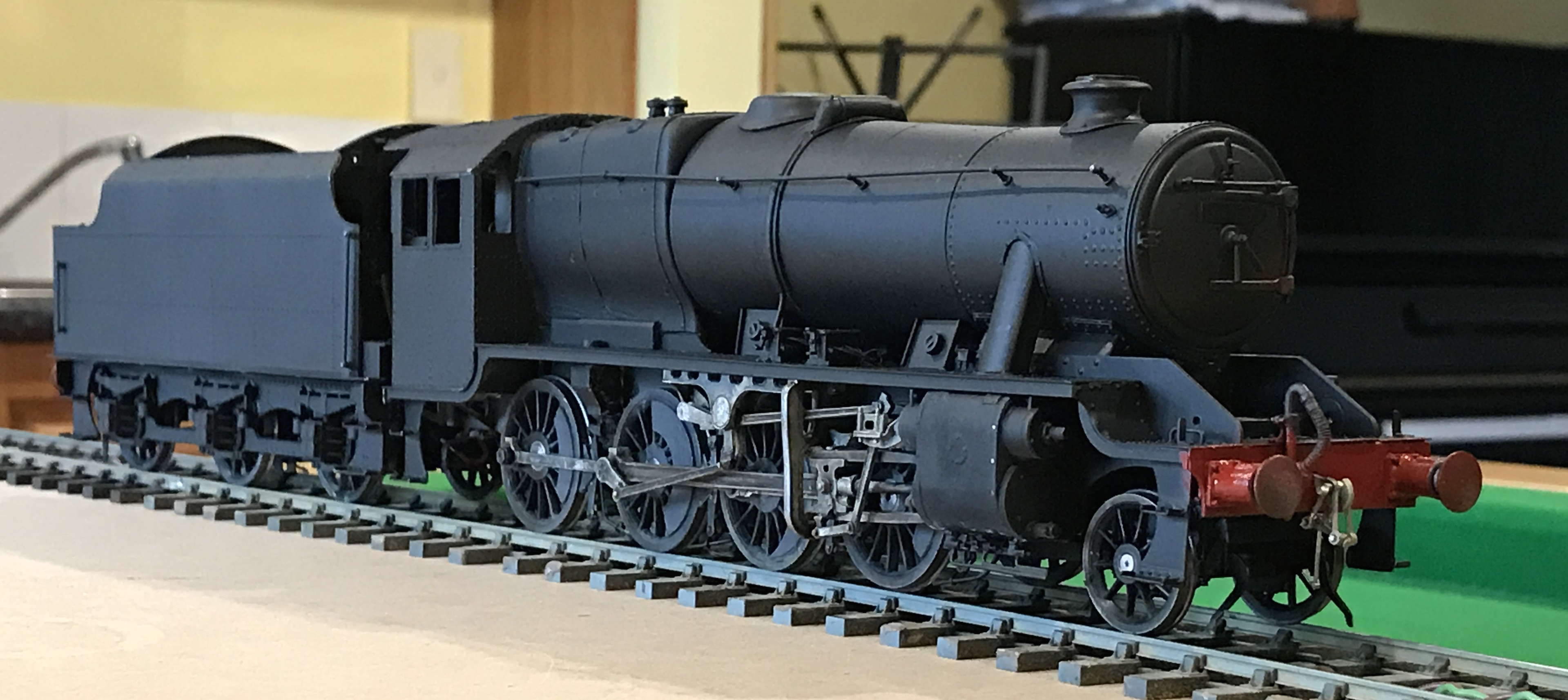
This is the stage at which realism becomes more possible. I have now painted the locomotive all over in matt black. I will then add numbers and lettering, before applying an all-over protective coat, then add weathering to make it more realistic.
As always, click to enlarge.
Here are some pictures in still and video format:
These are “Youtube” videos of the engine running on my test track.
To the educated eye there are some mistakes visible, even apart from the lack of number and lettering, but they aren’t too obvious, I hope.
There are no cab window frames or glass, some small parts remain the wrong colour (coupling hooks, etc). No coal in the tender.
There’s also no exhaust steam injector below the left of the cab (it fell off as I was preparing the loco for the video – curses!).
Onto the painting! An exciting moment. I have put the metal primer on already.
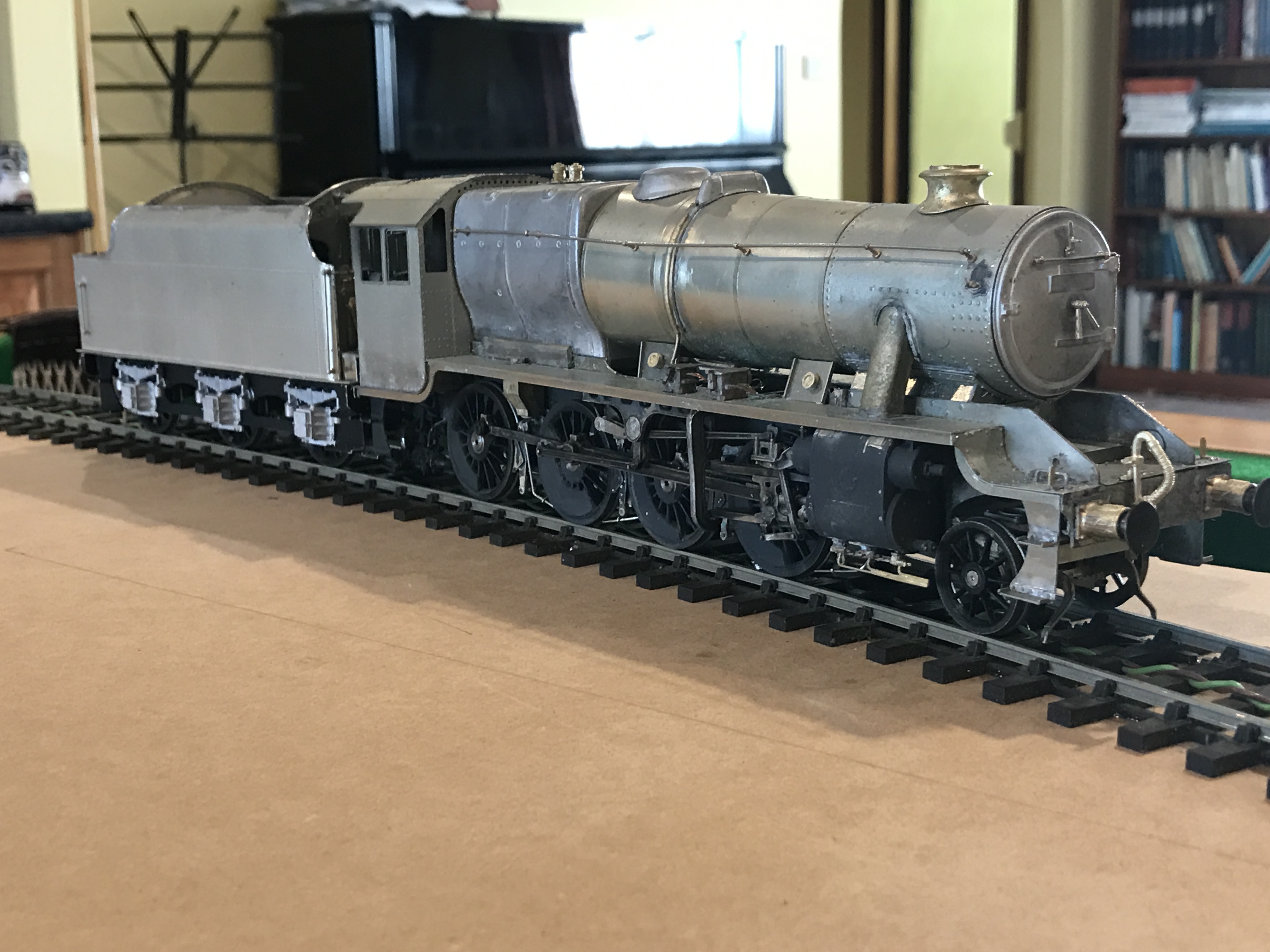
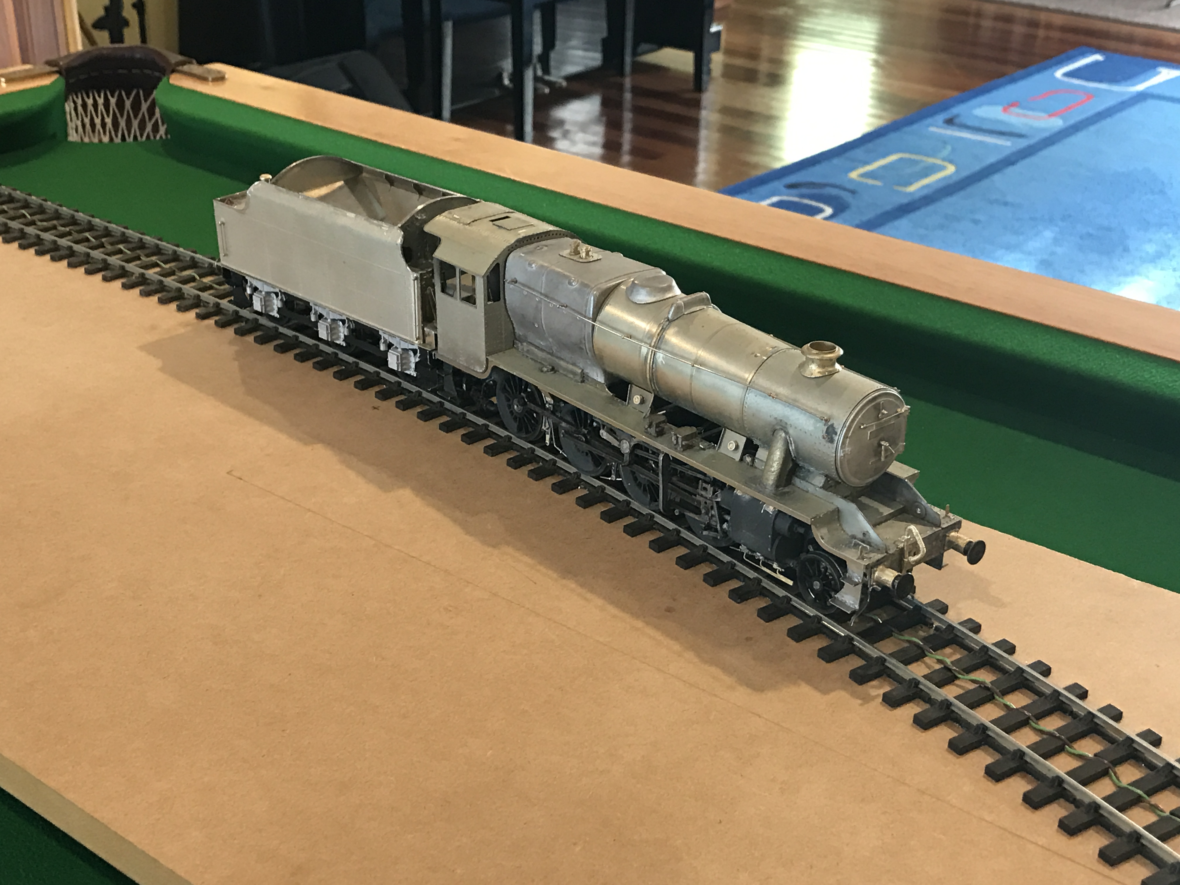
Here are a couple of pictures of the loco. and tender together.
The chassis and wheels have been partially painted already.
There are some modellers who assemble the entire kit before even starting to paint it, but this means that you are forced to take apart some of the construction in order to paint awkward places like behind the wheels, and so I have chosen to do a limited amount of painting as I go through.
For undercoat I use some stuff found in Australia made by a car-paint firm call Hi-Tech, who make some really good primer called (surprise) “All-Surface Primer”. I’m sure there would be equivalents made elsewhere. Advantages are that it will stick to anything (I have to use a Stanley knife blade as a scraper to get it off the polished granite samples that we have from when we chose our benchtop in the kitchen) and that it is really thin and so easily applied by an airbrush.
I am going to have to slacken off the coupling between the tender and the locomotive, because at present there is too little movement side-to-side to allow the loco. to go around the somewhat tighter-than-realistic curves on my layout.
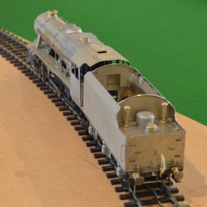
I think most of the details are done, and I have put it all together.
These are some pictures taken on my new iPhone:
And others from the normal camera:
So for the first time, it can run as a complete locomotive:
It doesn’t run smoothly because of electrical “shorting” between the front steps and the pony truck wheels at the from, when traversing the tight curves on my test track.
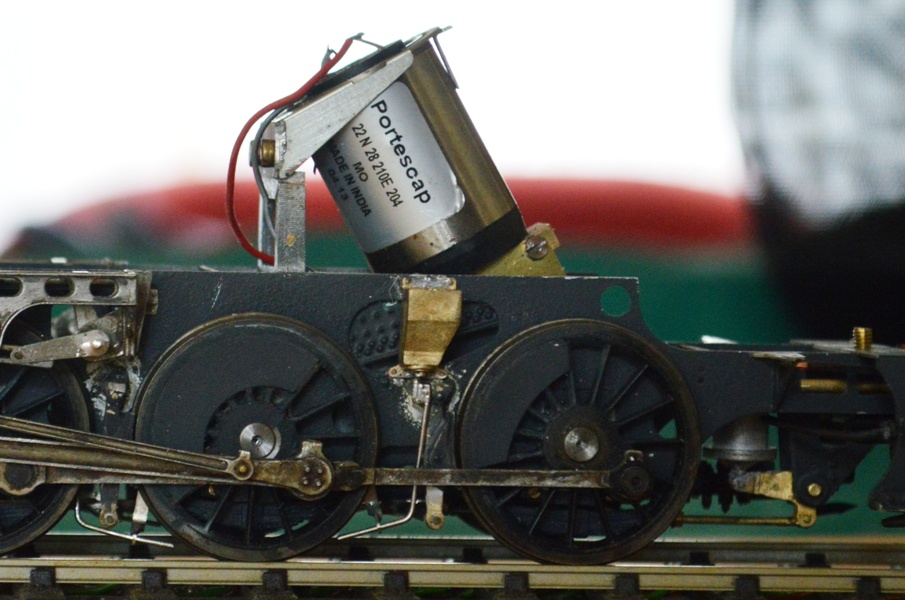
We are getting to the final stages of construction now.
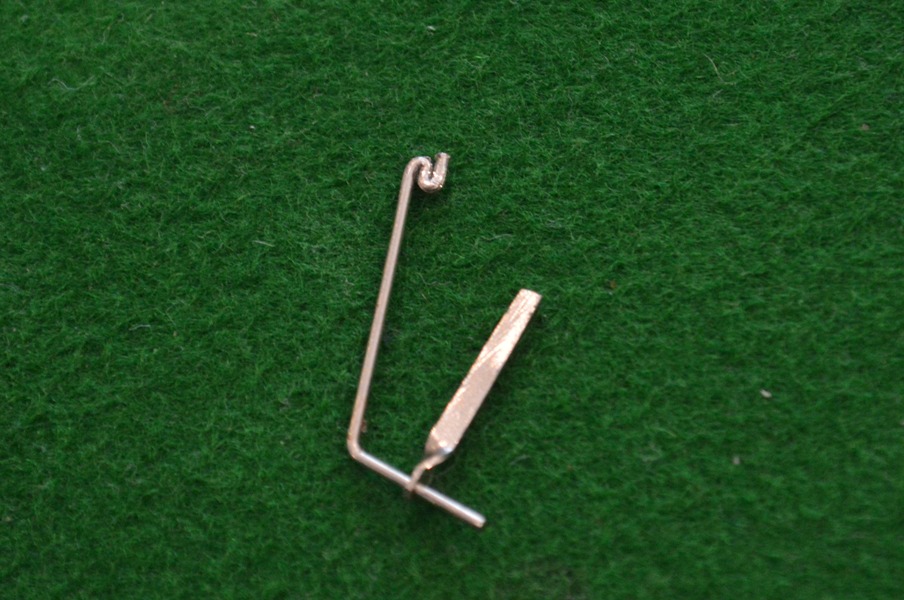
The details is being added to the body and the frames. I have added much of the detail, provided by the kit manufacturer, to the body itself. This is about adding the sanding gear. On the prototype, this is the equipment aimed to spray sand in-between the rails and the driving wheels to improve adhesion in slippery conditions. There are three sandboxes, with tubes going out of them down to just in front of the leading driving wheel, and both in front of and behind the third driving wheel.
In this kit there are brass castings of all three sandboxes, even though two of them are inside the frames. The outside one goes to behind the third driving wheel and has an additional mechanism (I don”t know what function it has) beneath the sandbox itself. The sand-delivery tubes are represented by 0.8mm nickel-silver wire bent to shape, and I made support brackets from thin strips of scrap n/s with 0.8mm holes bored in the ends, twisted and bent to shape.
Here is the one for the outside sandbox, with a folded-up section of wire to represent the additional mechanism.
Once bent up and soldered onto the frames, this is the (unpainted) appearance.
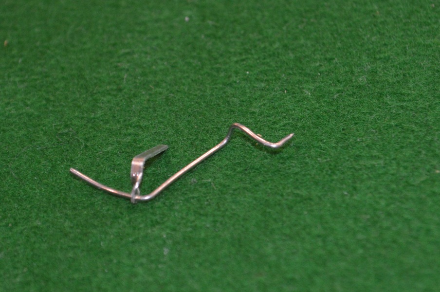
The central sandbox, supplying sand to the front of the third driving wheel, was even more of a challenge, and in the end I made wire with multiple bends in it, allowing one end to be anchored to the sandbox, with the other supported by a bracket in position near the driving wheel.
This shows the course inside the frames of the central sandbox “tubing”.
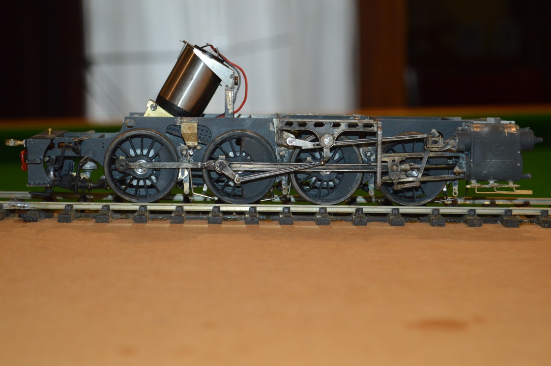
This side-on view shows all the three sanding jets in place. Of the sandboxes, only the rear one is outside the frames and visible.