I’m beginning to wonder just how obsessive/nerdy I can get.
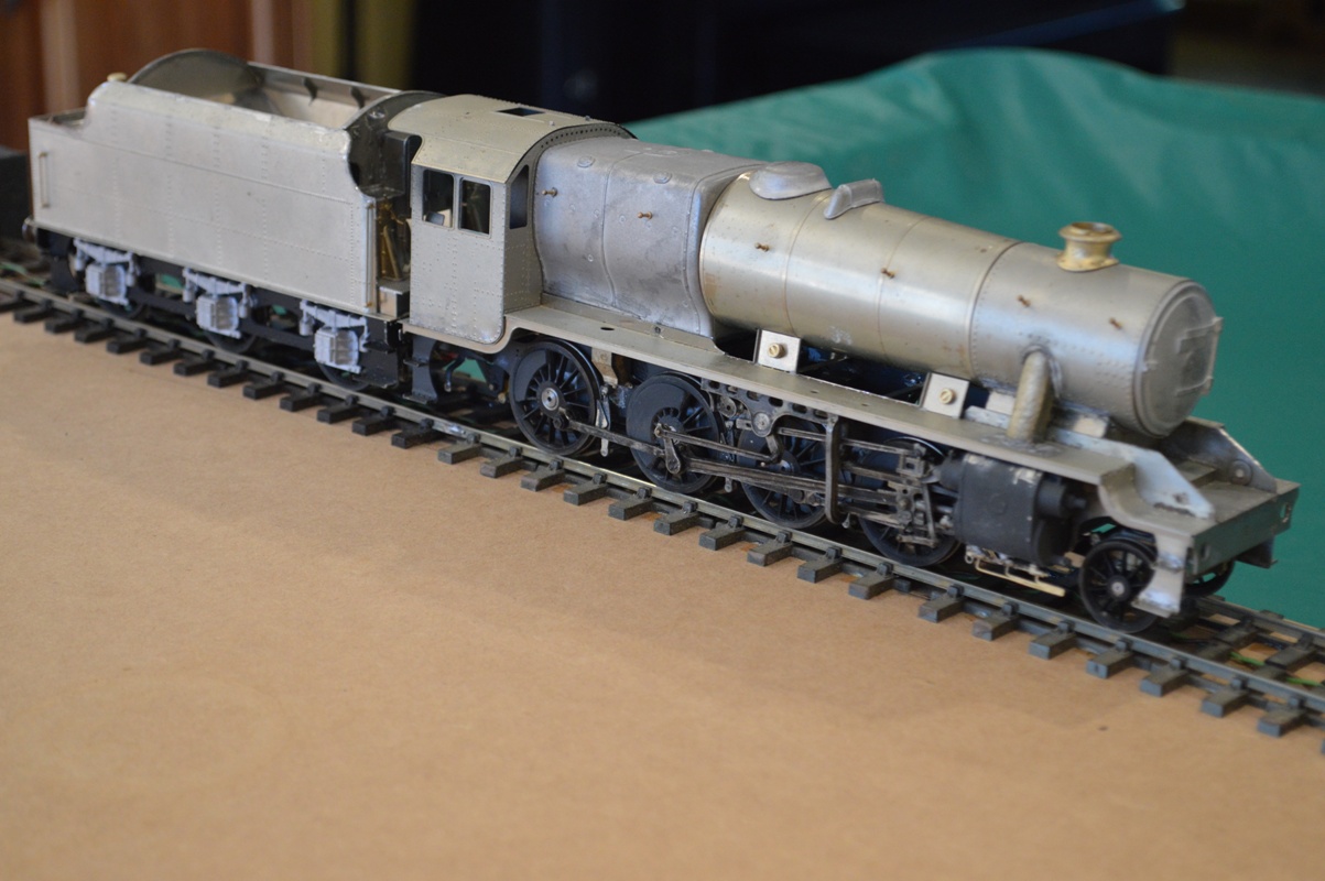
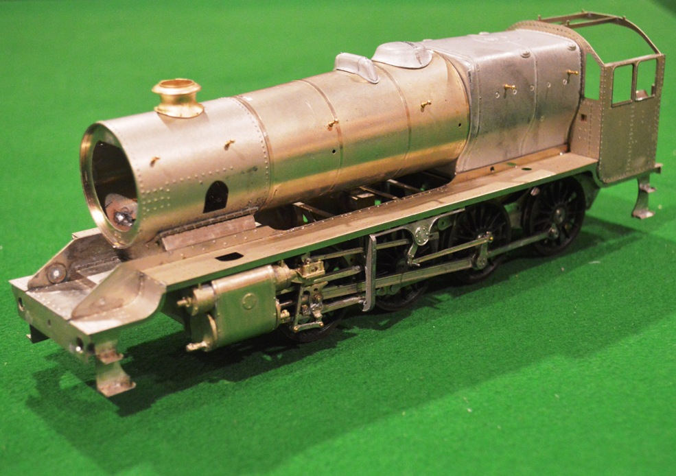
On my recent visit to England (see John’s ‘blog), we travelled behind one of my beloved Stanier 8Fs on the Scarborough Spa Express. I took pictures of the engine, and noticed many details that would be useful for my model.
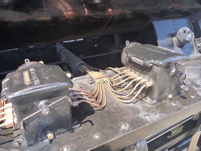 Amongst these were the mechanical lubricators and their pipes. They were all cleaned and nicely polished, and so were a quite prominent feature on the footplate of the locomotive. In working life they would probably have been grimy and not noticeable, I suppose, but now I had seen them, I felt I had to model them accurately.
The MOK kit comes with the two lubricators, but not with the pipes which go from them. So I had to somehow make the pipes from scratch. Stripping some mains cable I found multi-strand copper wire with which to make the pipes. Each strand was about 0.2mm thick, so approx. scale for a pipe 8-9mm across, which seemed about right. However, how to make them into the beautiful fan of pipework was not obvious, to say the least. I tried soldering the wires to the lubricator castings, but apart from clogging everything with solder, well you can imagine how successful that was. I then tried soldering the wire strands into ribbons six wires across, intending to use lower-melt solder to attach them to the lubricators. However I couldn’t solder the wires together over a short enough length then to make the elegant curved sections onto the castings. Lots of burnt fingers and strained eyes.
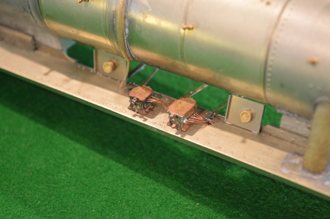
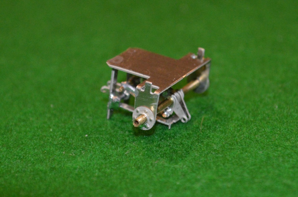
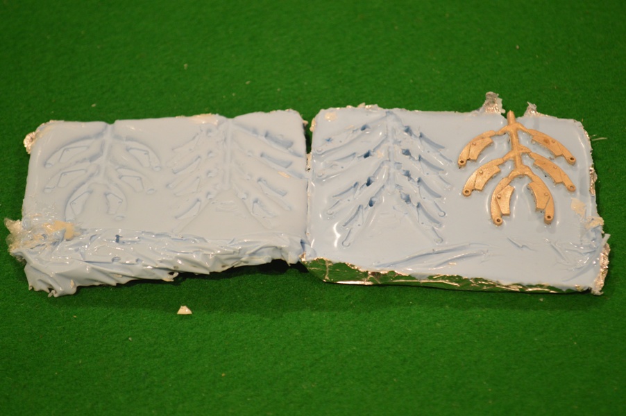
This is how I eventually did get something approximating to the desired appearance.
Click to enlarge.
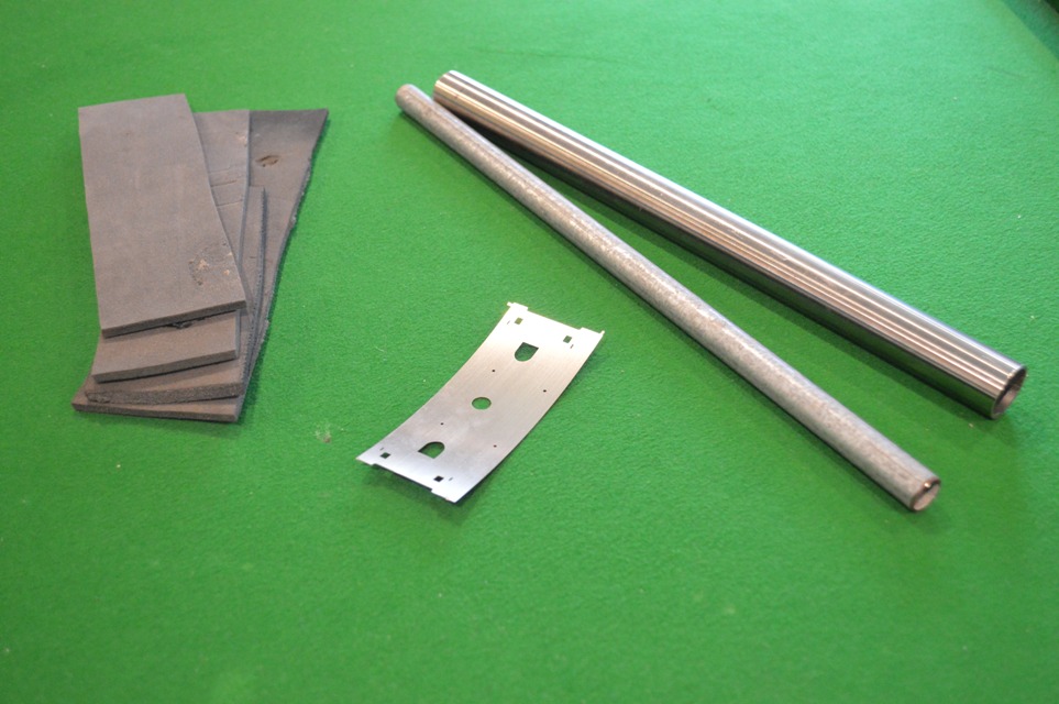
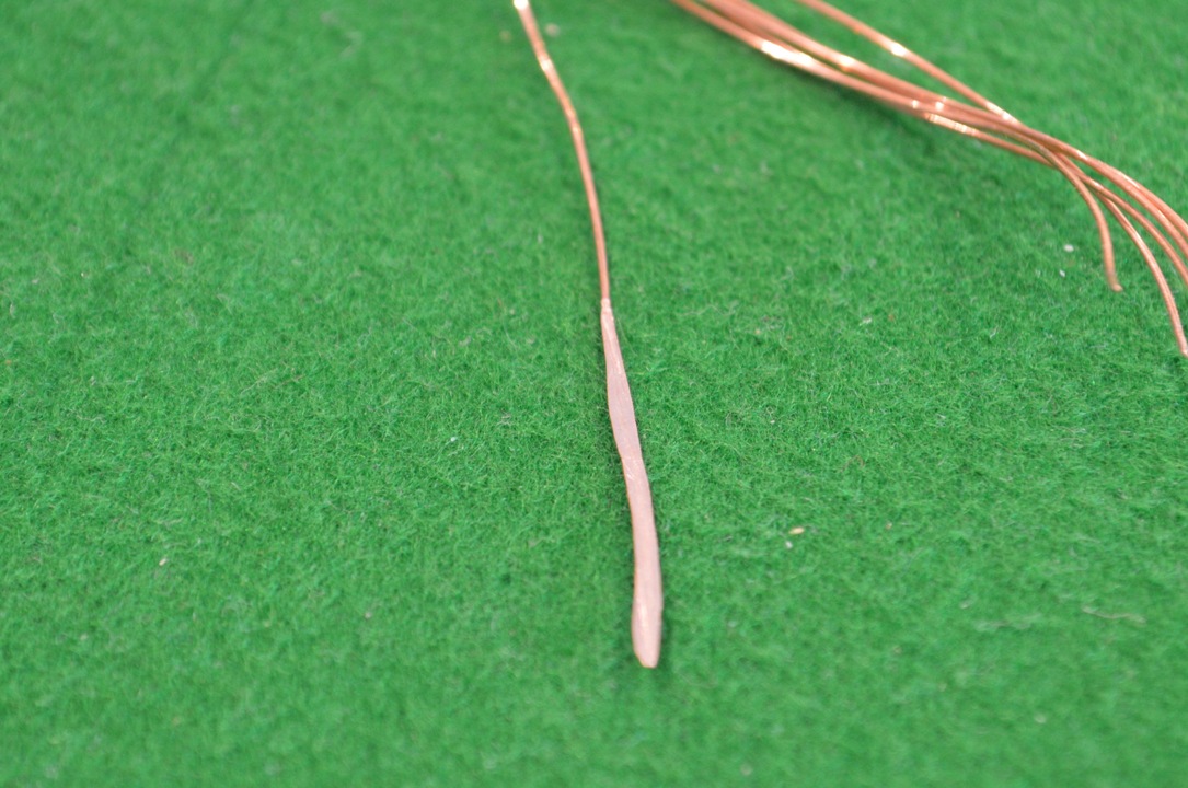
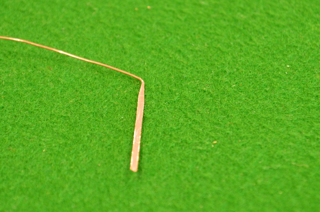
First I found some thicker copper mains cable, and flattened a section out with a hammer, evening its edges up with a file.
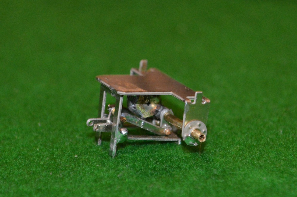
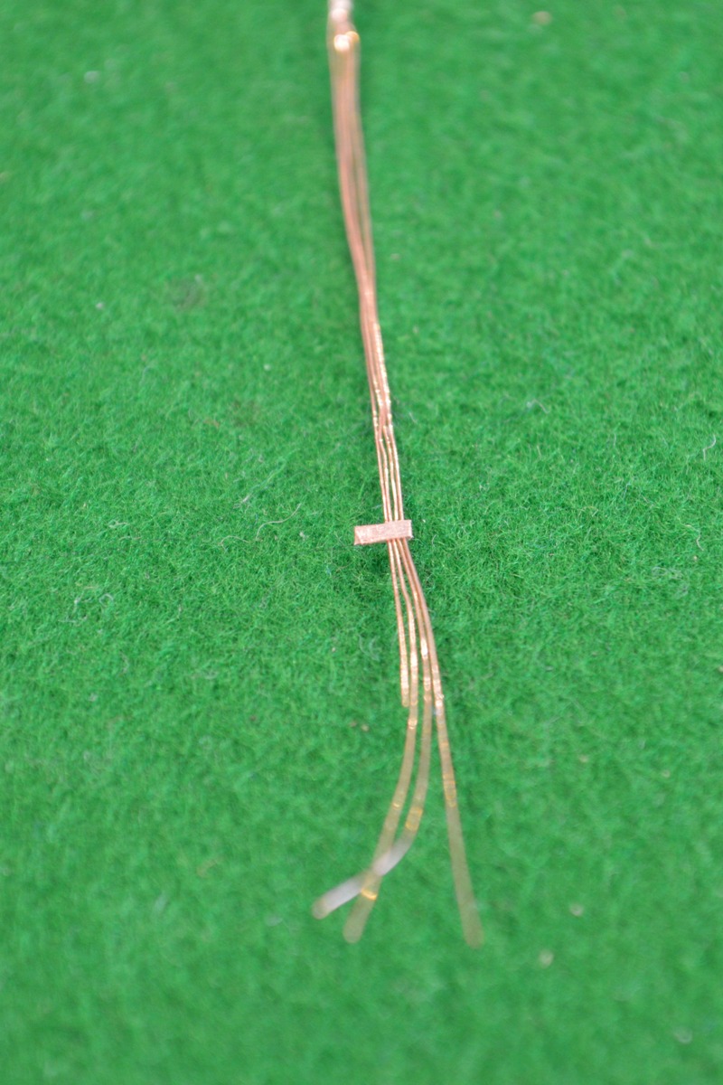
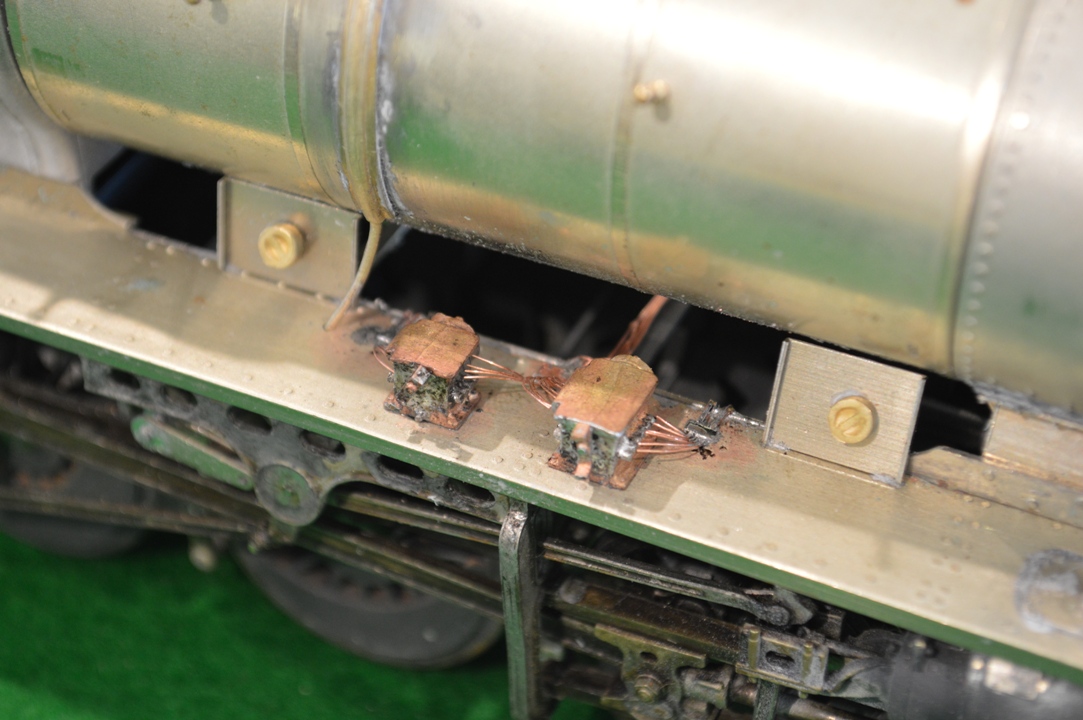
Next I cut a small section of this cooper strip and folded it over the necessary number of strands of 0.2mm wire and hammered the folded copper strip together to hold the wire, applying a tiny amount of solder to keep it all fixed. Then I could bend the curves into the ends of 0.2mm wire and separate them to go up to the lubricators.
 .
.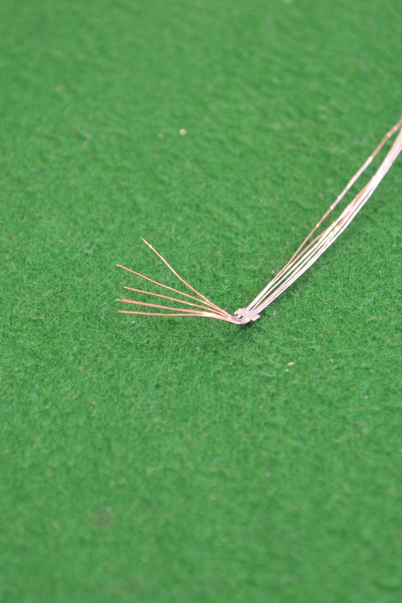
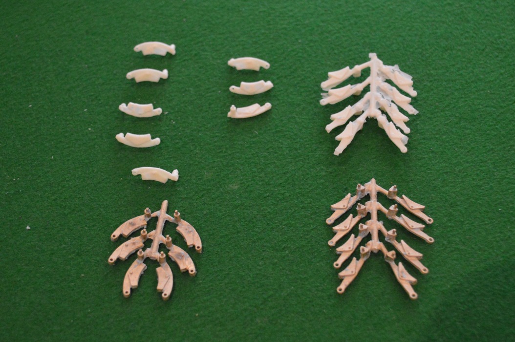
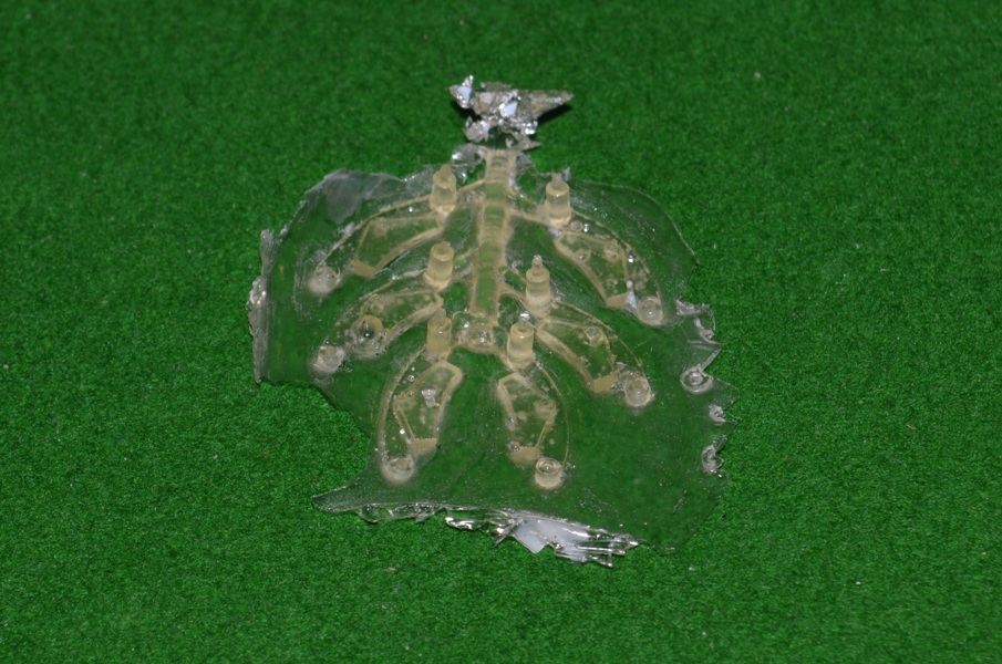
 The one in between the two lubricators had to take ten wires/pipes, divided to go different directions, of course!
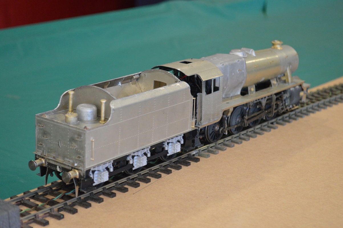
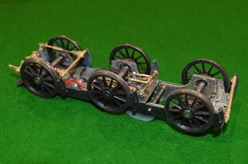
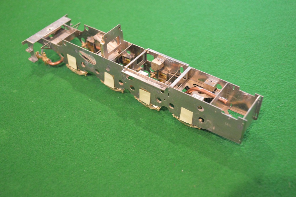
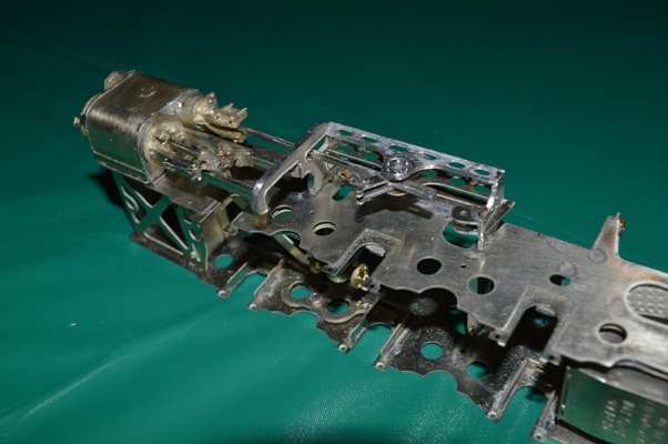
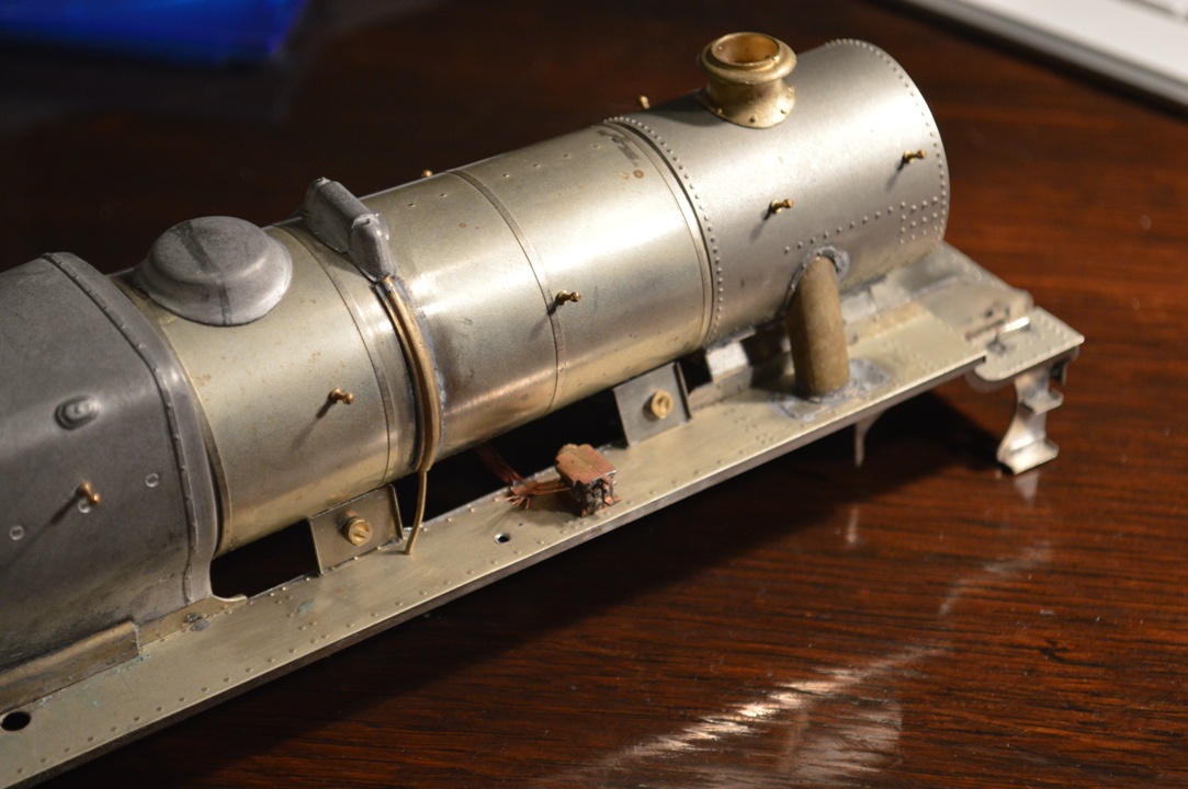
The fixing strips were then used to attach the pipes to the footplate, in a position so that the curved pipes are coming from the sides of the lubricators.
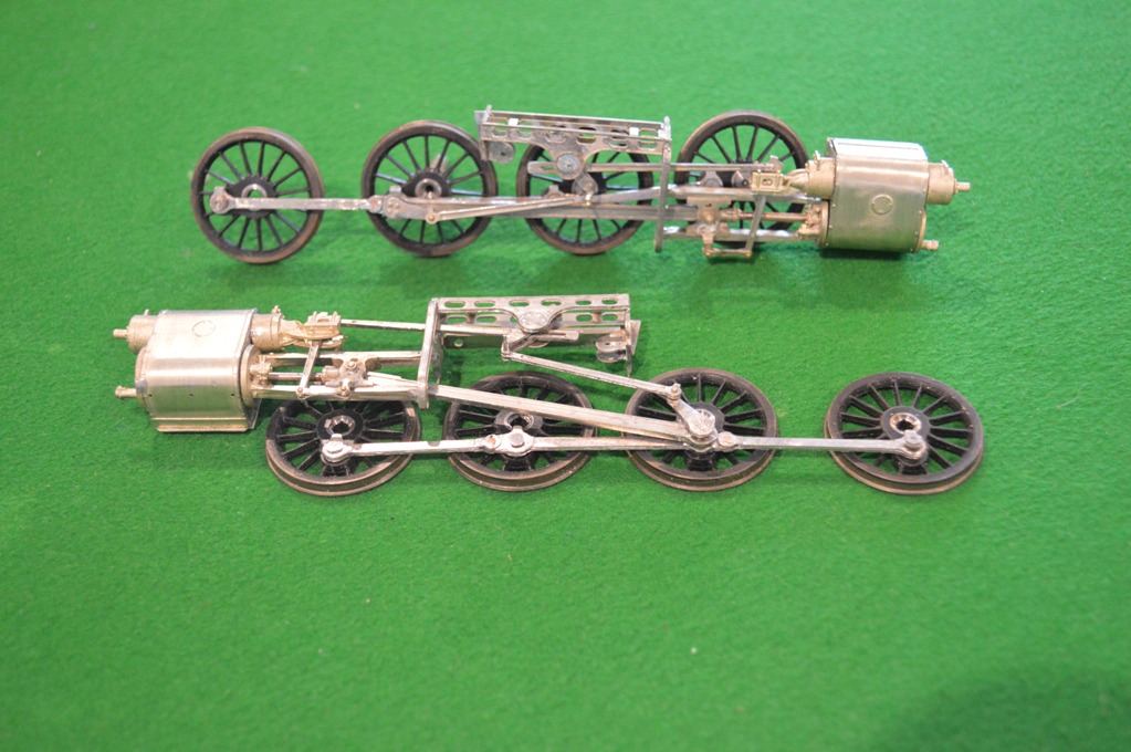
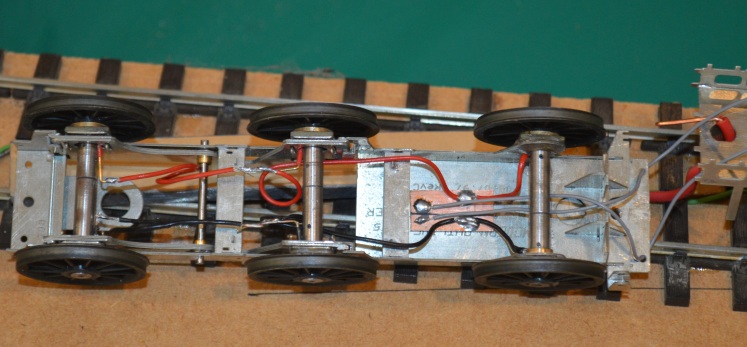
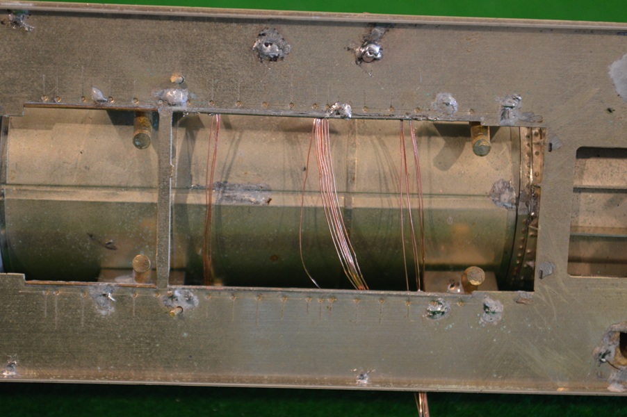 The other end of the multiple-wire constructions help to hold the curved ends in place when soldering, and can then be bent into shape to represent the lubricator lines as then do down or across the chassis – a few travel across to the other side over a chassis cross-member, and are visible from above.
 Was it worth all the trouble? I don’t really know, but it is satisfying to have succeeded, so if the painting eventually makes it invisible, i may just have to be content with that.