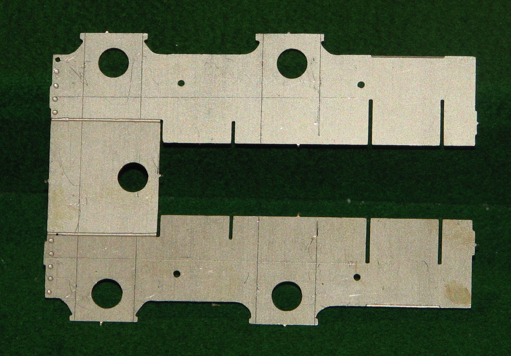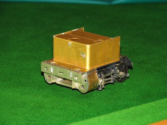
I have started on some of the bodywork for the tender. For someone like me, this threw up some significant difficulties due to my lack of expertise: how to bend the top edge of the tender sides? I have bent sheet metal before, to make the Belpaire firebox of my industrial Garratt, but this was brass, and not a particularly wide sheet of metal, either. The nickel-silver sheet for the tender side requires an even bend along a length of about 11cm. Dave Sharp from MOK has instruction about how to do it, but they are sketchy. The bend covers a height of about 3.5mm in the side, so I worked out that as the bend was through about 45 degrees, a bend of about 8mm diameter would be about right [8×3.5=28mm, divided by Pi = approx. 8mm diameter].
 The instructions show how to draw lines on drafting tape inside the bend, to position it accurately. This is good, but how to make the bend? My first try was to place a slightly smaller diameter drill to bend around, and clamp the tender side in my big vice.
However I simply couldn’t bend the nickel silver!
In any case, the drill wasn’t really long enough, and the ends might not bend properly. I was talking/e-mailing Richard at the time, and he suggested I buy a longer rod, of slightly smaller diameter than the bend I wanted to make, and then either roll the sheet over the rod using a rigid metal plate to transmit even pressure, or clamp the top edge of the tender side in the vice and bend the body over the bar. I suppose it was a little foolish of me to try to do it the other way around, but somehow it seemed right to bend the bit that is supposed to be bent, rather than bending the body down whilst holding the part which is supposed to be bent, upright in the vice!
I started to try to bend the sheet over a piece of 1/4 inch (6.3mm) aluminium rod which I found, on our granite kitchen benchtop (the household manager was out), but it was very difficult to bend, and also I thought that this technique might not produce a discrete bend in the flat sheet of the tender side (if you see what I mean), but rather make it a nice continuous curve in the metal sheet. It was impossible to hold the rod still relative to the sheet metal whilst trying to make the bend.
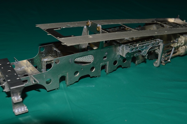
 So, back to the vice. The trouble now was to hold everything at once, to allow the rod and the tender side to be exactly positioned. So I used masking tape to hold the rod against the aluminium angle used to make smooth jaws in my big bench vice, as shown on the left.

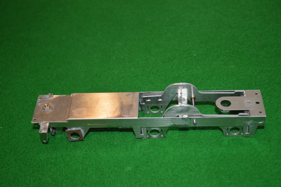
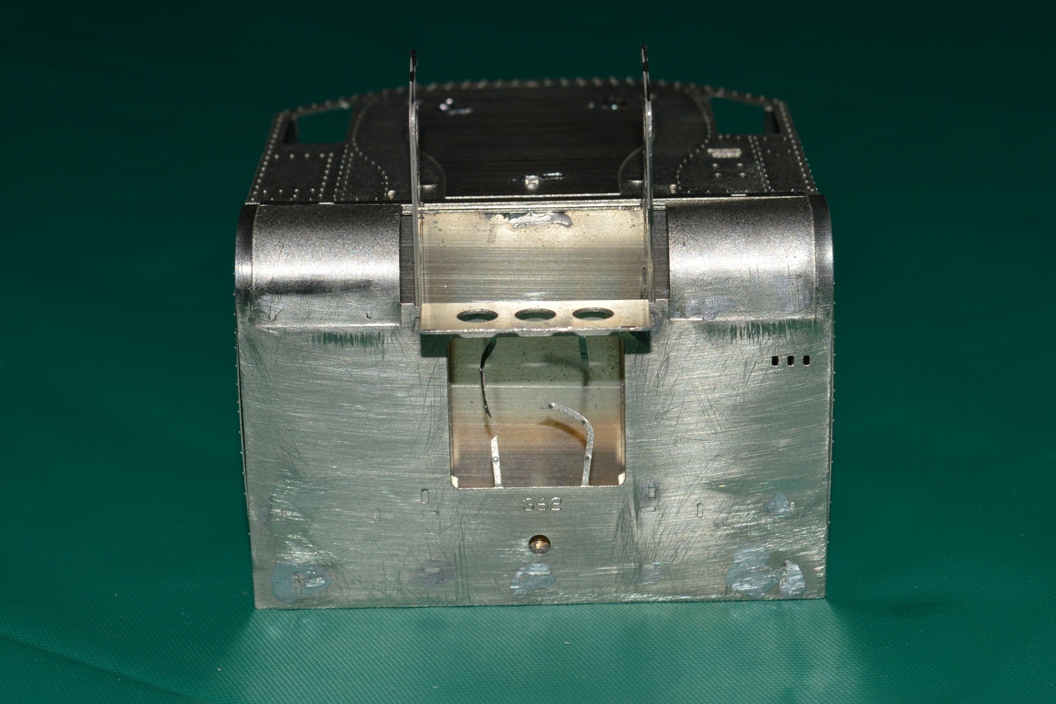
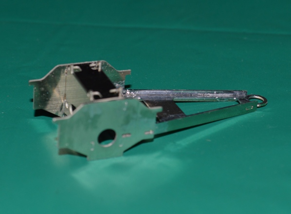
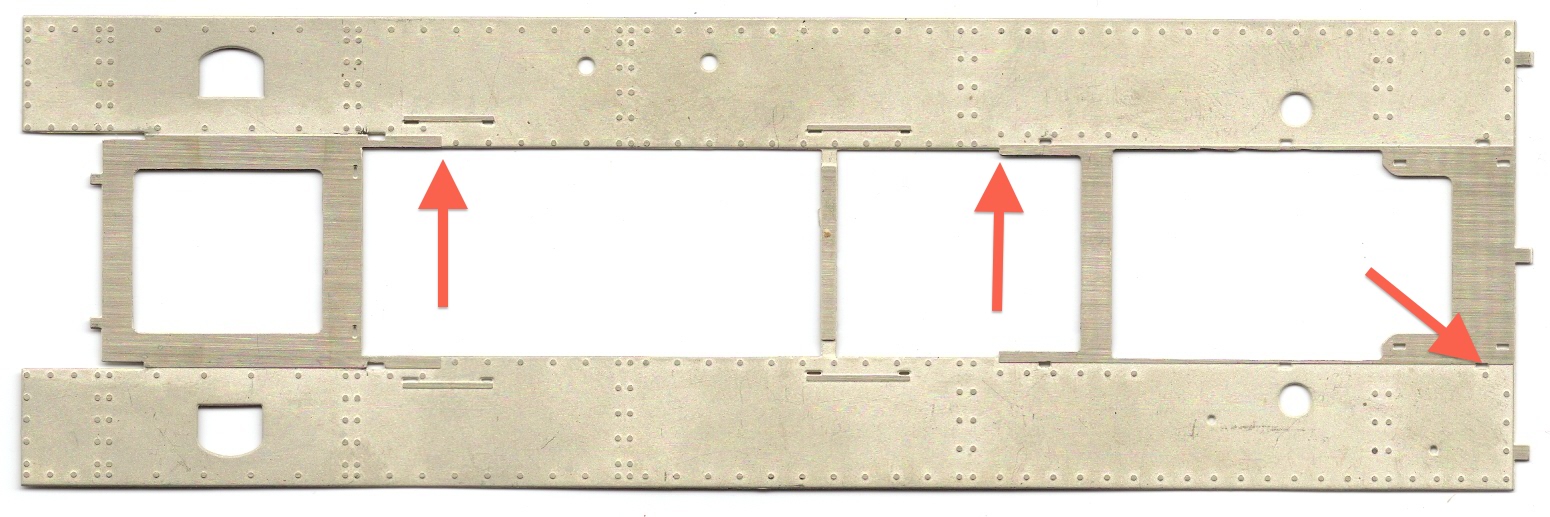
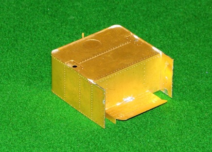
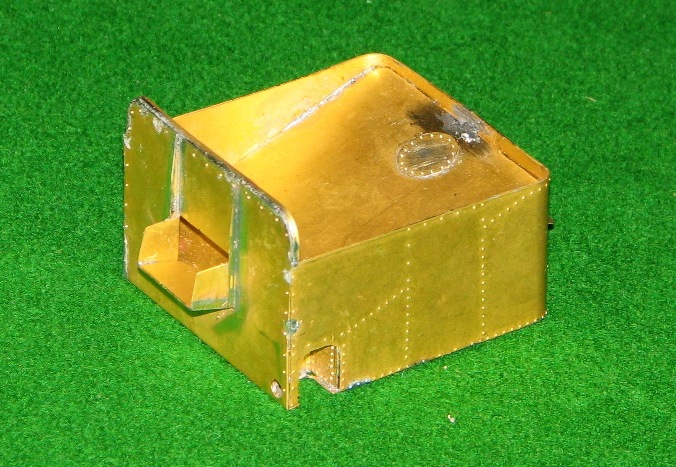
Then I put the tender sides into the vice and could adjust the position so that the start of the curve was held in between the rod and the vice, the other end of the curve being above this (in the picture one can just make out the second line):
This finally allowed me enough leverage, using a thick rigid steel rule, to make the bend in the tender sides.

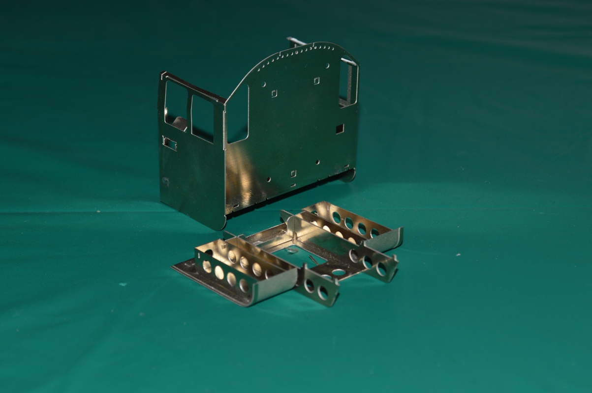
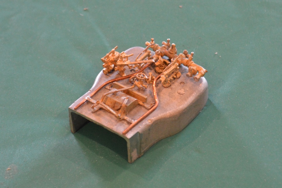
 It also allowed me, using the same technique, to form the vertical curves at the front of the tender sides (a bit out-of-focus in the picture, sorry).
HAPPINESS !
David