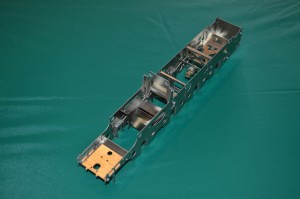
Scale Seven Model Stanier 8F Locomotive Part 8 – the wheels

Small Slaters S7 8F wheelsThe Slaters Wheelset has arrived, and very nice it looks too.


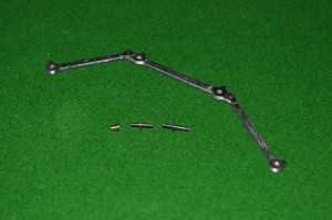
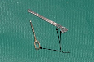
Coupling rods (articulated as shown), crankpins and crankpin bush

Coupling rods (articulated as shown), crankpins and crankpin bush

They come with an innovation (to me) from Slaters: crankpins which can be screwed into a boss set on the crank.


However Small Crosshead and S7 8F wheelsfor wheels on an S7 version of the MOK kit, they create a problem, illustrated in this picture:

The crankpins are clearly too long in this case, and their rotation will be obstructed by the crosshead and slidebars.
Now I am familiar with this problem from when I widened the frames and cylinders, etc., for my S7 Industrial Garratt, and actually this doesn’t look quite as bad as that one did. However I will need to shorten the special crankpins made by Slaters (if you look closely I will need to cut them back to move a bit more that the threaded part of the pin), and then I will need somehow to reproduce a thread on the end of what remains.
With the old Slaters system it would have been easy, but here the crankins are completely different.  The part threaded to go into the boss in the wheel is 10BA.  The smooth part of the pin, to go inside the coupling rod and connecting rod bushes) is also 1.6mm O/D, but the retaining nut screw-thread is 12BA.

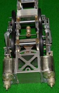
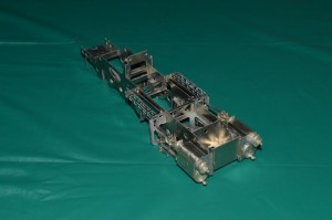
After seeking help from the experts/enthusiasts on the WesternThunder website, below is my first plan [I suspect that this is destined only to be the first plan]. The picture shows the frames with wheels in place. The front end is on the left. I am going to take advantage of the special construction of the S7 wheels, with the 10BA tapped holes for the crankpins.

Coupling rods and crankpins 02

I am lucky in having my friend in Melbourne Richard Davidson who has done some work on his lathe for me. Below the frames in the picture are the special crankpins which Richard has made for me.
My illustration shows how I hope to arrange the crankpins. From the front: axles one and two have the special crankpins in place. Axle one the pin is part-way through the coupling rod. Axle two has the crankpin all the way home. Axle three and four have the Slaters crankpins. The ones for the connecting rod wheels are longer, and will take two brass bushes on top of each other, through the coupling and connecting rods. The final axle will have a standard Slaters crankpin and bush.
Clearances will remain extremely tight at the front end. I intend to try the front crankpin fitting direct to the wheel without a washer. The boss on the coupling rod is slightly thicker than the body of the rod itself, so as it goes round it should be clear of the central wheel boss. The second wheel will need a washer, though: the articulation of the coupling rod will catch on the central wheel boss otherwise. By the third axle, fortunately, the clearances should be less critical. So the flat portion of the Slaters crankpin, acting as a washer, will be less critical.

I hope that it all works …..

Model 8F Part 7: Cab re-construction

Following on from part 6, I found out from MOK (Dave Sharp) that I had definitely put the base of the cab on upside down.  This has all sorts of minor but annoying effects.  One was the fact that the formers inside the base of the cab had been made to accommodate the etched plates which were meant to go inside the curved sections (making them invisible – they are there only to make curving these areas easier).  So the formers made the curved plates have a larger diameter of curve – hence leaving a gap at the outer end: exactly where I had found one.

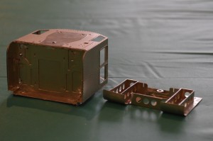
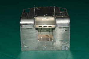
Small Cab reconstruction 002After much debate inside myself, I decided that I would never be happy if I did not do the job properly, so I pulled all the cab base apart using a 75 Watt soldering iron.  Once back to the component parts I tried to clean all the solder off the nickel-silver, then I flattened the bottom plate completely (apart from the front plate [see below]) first with my fingers, then with Small Cab reconstruction 003a tap hammer on a piece of flat granite.  The front plate (with three holes) is now bent upwards as it should be.

I then reformed the curves, fitted the formers back (now easier because the former correctly fitted onto the curved sections.  At the point shown in the picture, my soldering iron stopped working.  So I have sent off for a replacement.

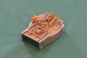
Whilst I wait for a new 25 Watt soldering iron, here is a picture of the completed boiler backhead.

Small Backhead painted 1I am quite pleased with it.  Basically I followed what fittings I could see on photo.s of preserved and other engines, and then upt as many pipes as I could on the brass castings, to be realistic.  I “painted” it using metal blackener, scraped some off the copper pipes and painted the dials and water gauges by hand.  A thin covering of matt varnish to complete the work.

Model 8F construction Part 6

I may have made a mistake, which has exposed a difficulty/problem with the etches, not related to ScaleSeven however.
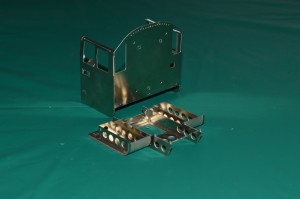
Cab underfloor
The first picture shows the overall basic construction of the cab: there is an undefloor part which I guess if faithful to the protoytpe, but is completely hidden one the parts are put together!

Small Cab pictures 01 On the underneath of the cab is part no 362, which is curved upward to make the curved plates leading up to the footplate.

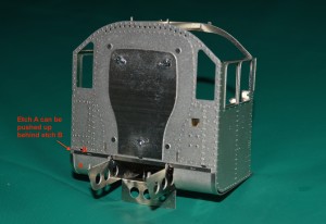
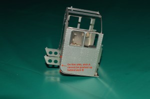
This shows that I may have put part number 362 on the wrong way up. I am guessing this because the three holes to take the damper levers have ended up on the wrong side. However putting it the other way up would mean that the fold for the panel at the front with three round gaps in it would be on the wrong side to bend it downwards – ie the bend would be away from the etched line. This is why I used it the way up which you can see in my pictures. Also the half-etched areas at the front on the curved plates I thought must be on the outside, because otherwise they would be completely hidden!
Small Cab pictures 02 So, if my analysis is correct, either the three holes for the damper levers are on the wrong side, or the etched line to fold the front plate is on the wrong side.
If you look at picture No.s 3 and 4, you can see that despite my care I have ended up with a gap between the cab-side etches and the curved part Small Cab pictures 03of part number 362.

On the right side this doesn’t matter, because if I push the curved part upwards, it neatly fits behind etch number 367 (this is the front of the cab, immediately behind the whitemetal firebox I think). This allows the shiny (unetched) strip at the side of the curved part on 362 to line up with the shiny strip along the lower edge of part number 367. Fine, it looks made to do just that. There will then be no gap along the bottom of the cab-side etch. The trouble is that on the left side, the curved part on 362 just abuts the thicker edge of part number 367 rather than going behind it, and leaves the curved part on 362 with a gap between that and the cab-side etch. This could be cured by removing a mm from the upper edge of part 362, but I’m reluctant to do that without knowing that it really needs to be done. Also with the assembly done so far, it will be awkward to do.  However advice from the Scale Seven fraternity on the Western Thunder website suggests that I have put the base on upside-down and the removing a mm from the curved part is therefore exactly what I will have to do.

Small Backhead 01

While I wait for the S7 wheels (for them to be sent to Aus., I want the whole lot at once, and I gather Slaters haven’t produced the pony truck wheels yet, although the others are ready), I have also been putting the details on the backhead.

It looks good so far, but it has been difficult to identify exactly where all the tiny lost-wax castings go.

I need to find views of the inside of an 8F cab, showing the backhead.  The “Locomotive Profiles” books have two, but one is of an oil-burner, and the other one doesn’t seem to have the same components as provided in my kit. Mostly it is the same, but some parts are seemingly missing from the kit (the one described in the book as the “independent steam valve”), and doesn’t appear to be a casting either for the “blowdown valve” or one which goes where the steam sanding valve should fit, between the left water glass and the brake handle. There is a casting which can be seen in my picture placed in position, but if fixed there it will obstruct the regulator handle.

The pictures that I found via Google images didn’t help.  Again I have turned to the WT website for help, and I am a little closer to answering my questions now.  Later versions of the 8F don’t have the sand gun control valves in the centre of the backhead, and there are some other little details which I will have to change.

More pictures when it is done ….

Stanier 8F footplate modifications

I have to say that I feel a little foolish about this, but as a warning to others ….  See if you could/would have made the same error.

Footplate etch

Original Footplate etch

The frames of my model 8F in Scale Seven I have decided to make at 29mm outside width (see previous posts).  The nice etch of the main footplate made by Modern Outline Kits is for their Finescale construction, so the inside edges of the footplate would be too narrow for my model, and would hang over the insides of the frames.

Footplate etch with extra rivetsIt might not matter too much, but I thought this should be easily corrected, so I decided to re-form the line of rivets which runs parallel to the inside edge, then cut back the edge wherever it shows.  I don’t have a rivet-forming tool which can precisely measure out and positon the rivets, but by careful measuring and scratching marks on the underside of the footplate, I seem to have managed a reasonable job.  I also scratched on the footplate the width of the frames, ready to cut back the inside edges.

So far so good.  I thought.

Footplate modified

Footplate modified

Next I cut back the frame edges, carefully cutting (piercing saw)  and filing straight edges.

Trial fit to frames: mistake exposed: what width should I have made the distance across the inside edges of the footplate?

NOT 29mm!

It should have been 29mm less twice the thickness of the frames – 27.5mm.  So the footplate now ended just outside of the frames!  This would look even worse than the overhang which I had decided to remove.  What can I now do?

Footplate corrected.

Footplate corrected.

I found some 0.7mm nickel-silver wire which I had left over from a previous project, and carefully soldered it along the inside of the frames.  Look carefully at the last picture (click to enlarge any of the pictures) and you might be able to spot the differences!

Oh, well!

Stanier 8F in Scale Seven, Part 4

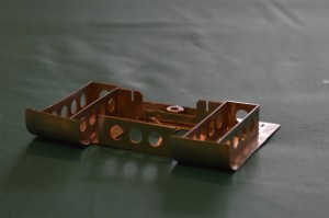
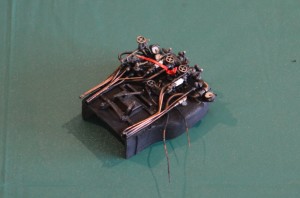
Onto the next bit. Whilst I wait for the S7 wheels to become available, I have tried to progress with other parts of the engine. The next bit in the instructions which I have is the pony truck. So I started on this.
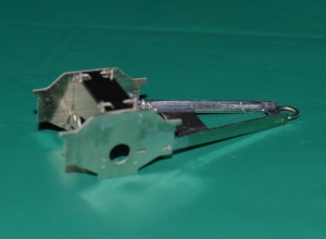
Small Pony Truck 1Here is the basic construction.

As can be seen, there is no compensation on the pony truck. I doubt that this is necessary, because there will be a little bit of lateral sway of the mechanism once in place, and so with only one axle surely compensation will not be required?


So should I add weight to the box-like centre of the pony truck?  I decided to do so, and carved a piece of lead weight from a truck-tyre balancing weight obtained from our local tyre-fitting place, to fit in the centre of the pony-truck.

Of course I’ll have to wait a while before seeing if this works!
Incidentally, I have a works diagram of the engine, and the frames of the pony truck in this kit are the correct distance apart (±0.5 mm, which is good enough for me) without modification.

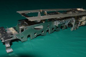
Next I constructed the rear steps, and the moved on to the front footplate sub-assembly. This is a great example of how the parts can be put together “dry” – no solder – because of the excellent tab-and-slot construction.
Small Footplate and frames fitting 2

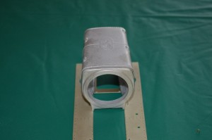
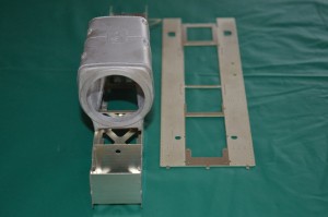
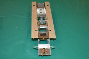
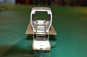
Frames and footplate from opposite the rear steps. The footplate is stopped from fitting down onto the frames by the upright used to hold the motor.

In making this sub-assembly, I came across a minor problem.
Small Footplate and frames fitting 1

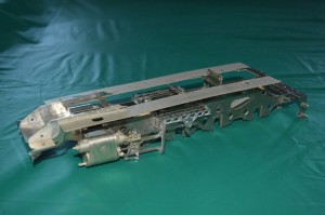
Frames and footplate seen from the front quarter. Note the front footplate sub-assembly is in place on the main footplate etch.

As can be seen in this picture, the problem is that the upright frame for the motor mount has a width of 29mm, whilst the distance between the edges of the footplate is 26.5mm.
It’s not a major problem, at first glance, and probably the answer could be simply to make a couple of small cut-outs in the footplate – 1.25 mm each side is only a small amount.   However before doing this I asked on a Scale Seven Web forum called Western Thunder (westernthunder.co.uk) to see if there was an alternative solution which anyone could see. Making cuts in the footplate is all very well, but what the effect on the later construction and the overall end-appearance I couldn’t yet tell.


It was suggested that the inside width of the footplate had been narrowed (making the footplates on either side a little bit too wide) in order to fit the narrower frames in Finescale 0-gauge.  This proved to be correct, so with my correct width frames I need to file or cut off some metal from the inside edge of both sides of the footplate to make it match with the top edges of the frames.

The footplate is exactly the correct external dimension, but the footplate width on each side is 16.7-16.8 mm. Taking this back to the correct width of 15mm will remove the line of rivets.  I could probably re-create these, however.  Probably it would be best to line them up before I file back the inside of the footplate edges.  The nickel-silver sheet, even over the etched areas, is still 0.5mm thick.  This will affect the small slots used to locate some other parts.  I don’t know as yet what parts are affected, but I will just have to find that out as I go along, I fear.

I was just about to set off and form the rivets on the footplate, then take 1.5mm off the inside of each footplate side, when another factor entered my brain, and it is just as well (I think) that it did.
Small Footplate and frames fitting 4If I took 1.5mm off the inside of each side of the footplate, then the whitemetal cast firebox would no longer fit as intended on the inside edges of the footplate.
Small Footplate and frames fitting 6

This might not matter, because the firebox would still fit on the frames themselves.

So if I made the inside dimension of the footpale sides nearly the same as the inside dimension of the frames then I thought that it would work. The inside dimension of the frames is 28mm. The inside dimension of the footplate is 26.5mm as supplied.

So if I took 1.0 mm off the inside of the footplate each side, the edges would sit on the middle of the frame each side, which would probably look OK, and the firebox could sit on the frame edges.  The only (?!) problem to remain would be that the line of etched rivets on each inside edge of the footplate sits right on top of the line to which I would need to reduce the footplate inner-dimension. Tricky.

So it was tempting to leave the footplate as it is, just cut back the motor-mount.  However this would leave the footplate overhanging the inside of the frames, which would not look very good.  File the original etched “rivets” flat, then reform them with my special rivet tool?

In all of this, advice from members of the WT forum showed me that I was going to have to cut the motor-mounting back, and reinforce it from within the width of the whitemetal firebox.  A slightly daunting task, but eventually I’ve taken the plunge ….. Bitten the bullet ….. etc.
Small Motor mounting Mods 1I used some rectangular-section brass to strengthen the motor mount, soldered into place.
Small Motor mounting Mods 4Then I cut off the frame uprights, and part of the motor mount. As can be seen, the footplate can now lie on the frames. Good.


Even better, the firebox goes over the motor mount!
In this view it is possible to see how well this model goes into the ScaleSeven arena: the firebox is exactly the correct width, even though the model was originally intended for Finescale.

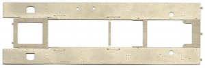
Inspecting the footplate now, it becomes clear (see diagram below) that I will only have to shave the 1mm off the inside of the footplate for the length between the two vertical arrows which I have put on the picture.
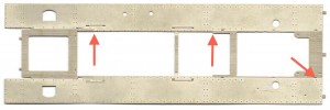
Footplate etch with arrowsThe rest is covered by the parts representing the frames above footplate level.

The angled arrow shows one of the slots into which the parts representing the frames where they are visible above the footplate will fit: just outside of the firebox moulding.
Interestingly, they are exactly 29mm across the outside dimension – as are the frames which I have built.

Of course I shouldn’t be surprised really, but it is reassuring.

Stanier 8F in Scale7 part 3

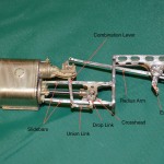
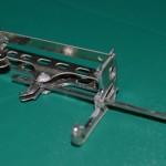
Cylinders, slidebar, crosshead and some valve gear.

Cylinders, slidebar, crosshead and some valve gear.

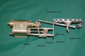
I have been contructing part of the valve gear, as shown.

The detail of this kit is such that the combination lever, with a complex shape at its top, if faithfully reproduced.  Unfortunately this means that the  where the lever goes through the crosshead of the piston valve (see the diagram at the top for the names of these tiny bits of brass!) it is such a tight fit that there is not enough movement in the model form.


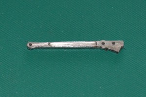
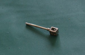
These are pictures of the piston valve shaft and crosshead (all one moulding) and the combination lever.  Unmodified as yet.

Combination lever - unmodified

Combination lever – unmodified

Small PV Xhead unmodified

Piston valve shaft and crosshead – all one piece of “lost wax” casting.


Small Combi lever and PV Xhead modified annotatedThey both have to be carefully filed back to allow the combi. lever to move through an angle of about 25 degree either side of verticle in the crosshead.


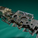
Small Frames with 2 cylinders

The story so far: frames with both cylinders, motion brackets and valve gear attached


Click to see progress.

8F progress

I’ve been working slowly on the “motion bracket” and the slidebars and crosshead assembly, toghether with some of the valve gear.

Here are some pictures of the progress so far:

Union link and radius bar - note the Y-shaped ends

Union link and radius bar – note the Y-shaped ends

Radius bar and expansion link.

Radius bar and expansion link.


Click to enlarge

Radius bar and expansion link in position, in the motion bracket.

Radius bar and expansion link in position, in the motion bracket.

Motion bracket, etc., in position on the frames.

Motion bracket, etc., in position on the frames.


A few notes of explanation.  The first shot shows the laminated rods, with bifurcated ends to allow joints with other pieces of valve gear: see the union link in the fourth picture (parallel to and below the cylinder slidebars); the expansion link is the curved piece through which the radius arm travels.  In most models the radius arm is left in a neutral position, thoguh the centre of the expansion link.  This is convenient, as the centre of the expansion link is the pivot about which it moves forward and back, but for the radius arm to be there is to have the model always in neutral gear.  So instead I am making my model in a forward gear, with the radius rod just below the central expansion link.  The radius arm will move forwards and back a very small amount as a consequence, but the construction should be able to be done reasonably easily (I think).

It’s possible to see this in the pictures if you look closely.  I had to create a pivot for the radius arm just below the central pivot of the expansion link.

Cylinders, slidebar, crosshead and some valve gear.

Cylinders, slidebar, crosshead and some valve gear.


The whole construction is made to come off the frames for ease of maintenance and building.

Not complete, of course.


Stanier 8F in Scale Seven – first post

I have started to build a model Stanier 8F locomotive in 7mm scale, 33 mm gauge – Scale Seven.  It is a Modern Outline Kits model, and Dave Sharp, of MOK, is being very helpful: it is a kit made for “0-Gauge”, and he is making a special conversion kit, to allow construction in 33mm gauge (a prerequisite of S7) with widened frames (29mm outside width).

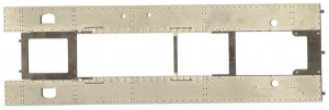
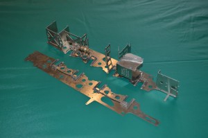
Frames in construction: the spacers between the frames have been soldered to one frame only.

Frames in construction: the spacers between the frames have been soldered to one frame only.

So far, the kit seems extremely well thought-through.  The conversion kit works well so far, also.  Correct frame width in 7mm scale would be 30mm O/D, but in discussion with DS, he and I agreed that to do this would leave so little room for manoevre that it would make the kit very difficult if not impossible to make.  This kit appears to have the girders and plates between the frames made to scale as far as possible.

Frame, showing the compensation mechanism and the insulated driving wheel bearings ("hornblocks").

Frame, showing the compensation mechanism and the insulated driving wheel bearings (“hornblocks”).

There is an elaborate method of “compensation” – a mechanism to alow the axles a limited amount of up-and-down movement.


Frames together: if you look carefully you can see the blobs of solder on the nearer frame.

Frames together: if you look carefully you can see the blobs of solder on the nearer frame.

These are the frames put together, all “squared-up”, but so far with solder only on the one frame (just visible as blobs on the outside of the nearer frame – I will have carefully to flatten them after construction, and there will be only about as millimeter between the frame and the inside of the wheels.

The kit clearly has the potential to make a superb model of this freight locomotive.