
I now have the radio control apparatus, seen piled on top of the superstructure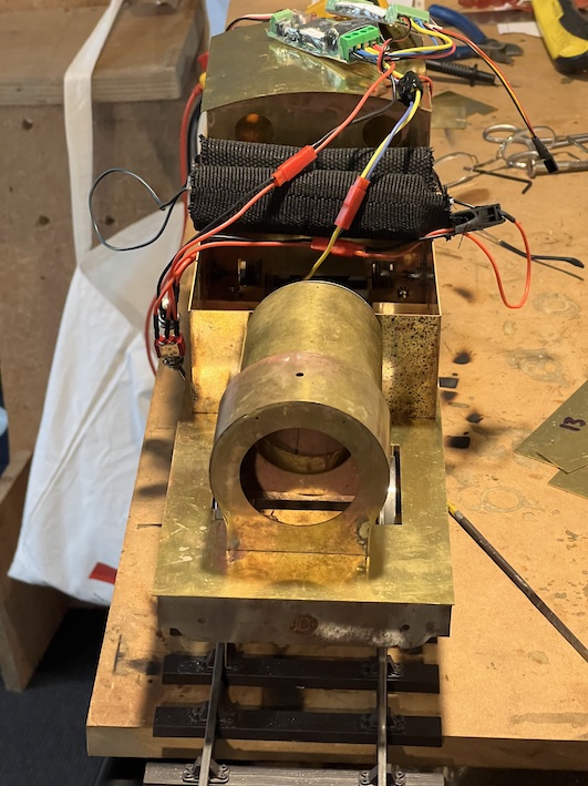 .
.
I have opted to have sound (!) as well as battery-powered radio-control.
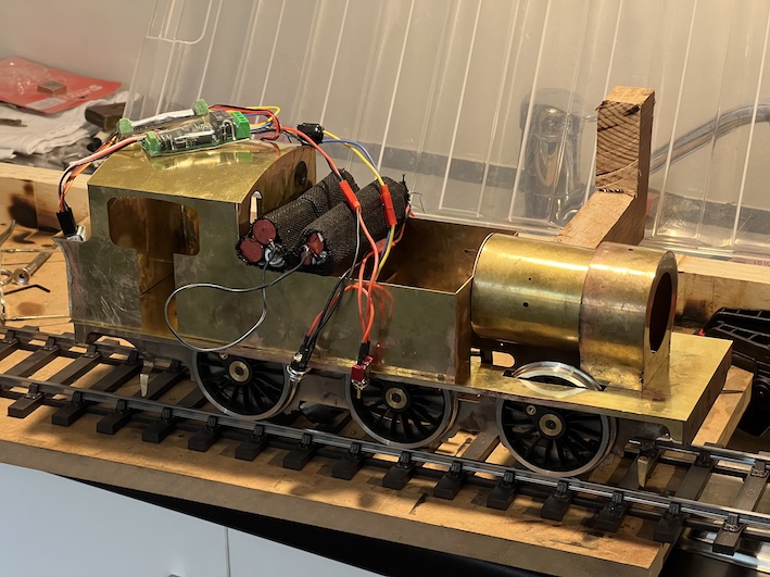 The battery-packs can be seen stacked on the outside edges of the side-tanks. The speaker for the sound is in the cab at this stage. The batteries will eventually go inside the water tanks. So far the electrics all seem to work OK.
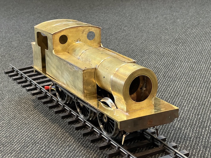
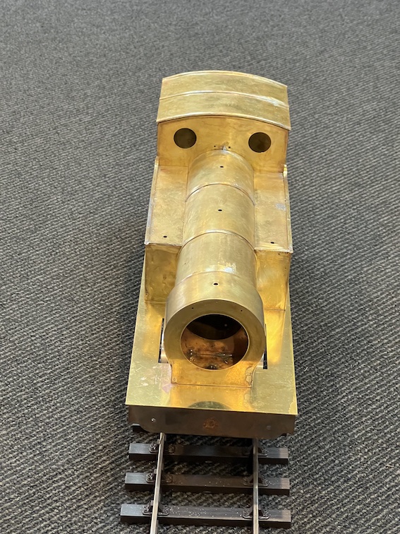
The kit is very well made from sheet brass (and steel). This is so true that when parts don’t quite fit I first blame myself for not building it well enough! So far I have had to use no molded parts, just sheet metal cut to size. Mike Palmer, I think it is he who packs up the kits for the Gauge 3 Society, had taped parts together to aid their identification – important when several oblong bit of brass, or pieces of thin brass strip have to be identified before assembly.
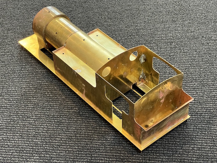
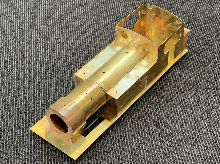 I started off the kit by silver-soldering the steel frames (see the previous entry in the ‘blog), and have carried on using silver-soldering up until now – I love the way silver solder “flows” into the joints once they bare hot enough. It’s also difficult to get the joints apart if you make a mistake though. As you can see, progress on the body continues, and the engine is beginning to take shape. Now that the main parts are done I’m intending to change to “soft soldering”, at a lower temperature, but I will have to se a large soldering iron, with a clean tip, as the large amounts of brass form a large “sink” for the heat. That is, it’s difficult to get the work hot enough for the solder to melt and adhere. I will need to use a better-cleaned tip on the iron than I am usually using.
The kit is very well thought-through, although in some ways this needs to be better explained than is done in the provided instructions. Perhaps I’m too inexperienced at putting these models together, but it might have made things easier if I had understood a few central principles like the fact that the from part of the boiler is separate from the rest, but when it and the made-up water-tanks-and-cab section are held onto the footplate (with half-a-dozen bolts) it is all held together and in-line.
 It is possible, now, to see the body mounted provisionally on the frames and wheels. There IS something of a problem, though …
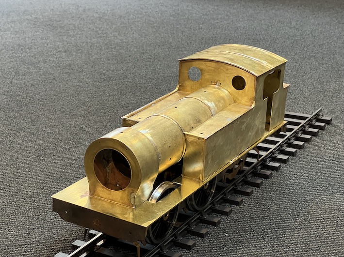 The rear wheel on the left side is missing!
I had put all the wheels in the frame, added the coupling rods and persuaded the whole assemble to turn under the power of the motor, using the radio control system and the rechargeable batteries I have bought.
After a while, though, it stopped, and on close inspection this had happened:
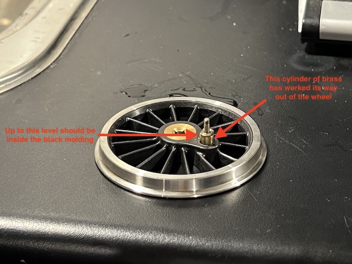 The mount for the crankpin had worked itself out of the black plastic molding which represents the wheel hub and spokes. Disaster. Can I get a new wheel from Slaters? The trouble is that this would take weeks at best. Can I just push the brass mount back into the wheel (and use cyano-acrylate glue)?
I suppose that whatever I do, at least I can get on with the bodywork …