
The instructions are a little terse at times, such as this: “Obtain a running chassis” !

After a struggle, this is where I am now at:
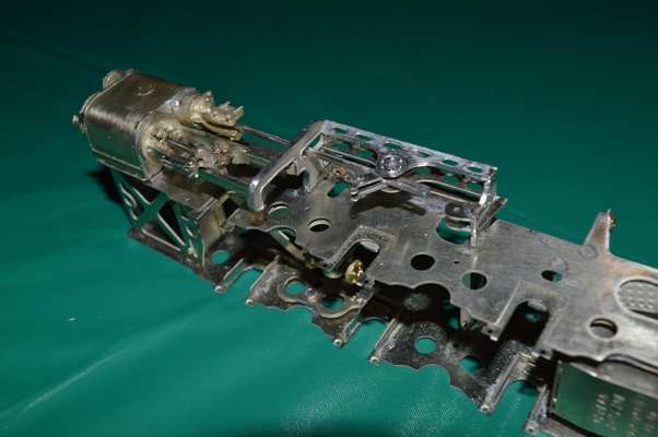
Motion bracket, etc., in position on the frames.
However it will take a little while to describe how I reached this point!
This is what I had constructed so far:
I had bought the special ScaleSeven wheels, but it turned out that the wheels rims/tyres had been made to S7 standards, but the central boss part of the wheels was far too thick. I was lucky once again to be able to enlist Richard Davidson’s help, and he used his lathe to thin down the wheel centres by about 0.5mm each. This extra space on each side would be crucial to allow the wheels and coupling rods to turn behind the slidebars and crossheads without catching. Even with the wheels thinned down, it is a very tight fit. It was simply not going to be possible to fit the manufacturer’s crankpins, washers and nuts.
 Once again, Richard has been the saviour. He manufactured four specials crankpins – bolts to go through the coupling rods from the outside.
I decided that on the first axle the special crankpin could be used without a washer inside, as the coupling rod was slightly thicker around the crankpin, giving clearance over the wheel centre. For the second axle, though, a washer would be needed between the special crankpin and the wheel boss, as the articulation in the coupling rod would foul the wheel centre otherwise. For the third and fourth axles the Slater’s crankpins could be used.
 Shown here are the different crankpins in place.
When I first put the axles in the frames, bolted the retaining plates to keep them there, attached the coupling rods loosely and turned the chassis over: JOY – the chassis could be pushed forward and the wheels all rotated with minimal binding. Too easy, as they say here in Aus.
“Too easy” in fact …. Once I tightened down the crankpins the binding started. I am not sure what the correct way to sort this out is, but Richard had once shown me how to push the frames along, and when the wheels stopped rotating, move each segment of coupling rod sideways with a pair of forceps to see if it moves: even a little movement shows that this is not the part which has stuck. When a crankpin with no movement is found, the hole in the coupling rod probably needs to be enlarged (with a small tapered reamer). I slowly opened out the holes in the coupling rods where the binding was occurring. At least with the articulated coupling rods this is made easier. However it also became obvious that on one wheel the countersunk central bolt holding the centre of the wheel to the axle stood out too far and was scraping against the coupling rod – the bolt had to be filed back just a little.
This all seemed to take ages, and the special crankpins were difficult to take out each time – I had to buy a “pin chuck” (like a very small drill chuck) to hold the circular heads of the crankpins. However in the end I did “obtain a running chassis”, although one without the connecting rods, etc in place. I couldn’t then resist a trial fitting of my Portescap motor and ABC gearbox, to see it all turn for the first time!
Using the Slaters crankpins and their “top hat” bushes made the coupling rods stand out an unrealistic distance from the wheels, so next action was to thin down the flange of the top hat bushes (almost removing the “rim” of the “top hat”!), and shorten them so that they are only slightly longer than the thickness of the rods.
 After all of this, fitting the cylinder/slidebars/motion bracket assembly revealed that all the work was being rewarded, with a small but definite clearance between the front crankpin and the crosshead on the slidebars.
The connecting rods were still not fitted, so next was to attach these to the crossheads. There was nothing in the instructions about how to do this. There is a post coming out of the recess in which the small end of the connecting rod fits, about which the rod will move. I cut this off flat with the crosshead rear (the was no way it could be allowed to protrude!). After some thought I measured the post: 2mm diameter, and made two tiny circles of flattened nickel silver wire (curled around a 1.9mm drill, then flatted between a steel ruler and a granite benchtop with a hammer (lucky the household manager was out again). I could then solder the wire circle around the post to hold the connecting rod in place.
 Connecting the connecting rod then allowed me to see the next difficulty – the expansion links have to be made very carefully so as to hang just wide of the connecting rod. I had not done that (it’s not easy to see this difficulty before this latest part of the construction), so some reconstruction is going to be needed now.