Onto the next bit. Whilst I wait for the S7 wheels to become available, I have tried to progress with other parts of the engine. The next bit in the instructions which I have is the pony truck. So I started on this.
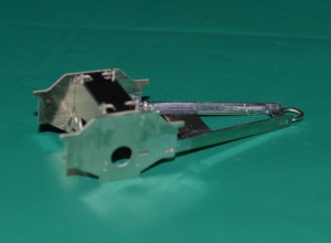 Here is the basic construction.
As can be seen, there is no compensation on the pony truck. I doubt that this is necessary, because there will be a little bit of lateral sway of the mechanism once in place, and so with only one axle surely compensation will not be required?
So should I add weight to the box-like centre of the pony truck? I decided to do so, and carved a piece of lead weight from a truck-tyre balancing weight obtained from our local tyre-fitting place, to fit in the centre of the pony-truck.
Of course I’ll have to wait a while before seeing if this works!
Incidentally, I have a works diagram of the engine, and the frames of the pony truck in this kit are the correct distance apart (±0.5 mm, which is good enough for me) without modification.
Next I constructed the rear steps, and the moved on to the front footplate sub-assembly. This is a great example of how the parts can be put together “dry” – no solder – because of the excellent tab-and-slot construction.
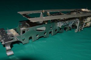
Frames and footplate from opposite the rear steps. The footplate is stopped from fitting down onto the frames by the upright used to hold the motor.
In making this sub-assembly, I came across a minor problem.
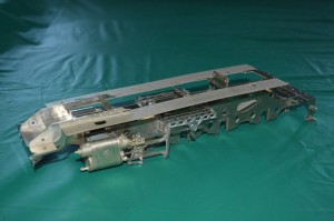
Frames and footplate seen from the front quarter. Note the front footplate sub-assembly is in place on the main footplate etch.
As can be seen in this picture, the problem is that the upright frame for the motor mount has a width of 29mm, whilst the distance between the edges of the footplate is 26.5mm.
It’s not a major problem, at first glance, and probably the answer could be simply to make a couple of small cut-outs in the footplate – 1.25 mm each side is only a small amount. However before doing this I asked on a Scale Seven Web forum called Western Thunder (westernthunder.co.uk) to see if there was an alternative solution which anyone could see. Making cuts in the footplate is all very well, but what the effect on the later construction and the overall end-appearance I couldn’t yet tell.
It was suggested that the inside width of the footplate had been narrowed (making the footplates on either side a little bit too wide) in order to fit the narrower frames in Finescale 0-gauge. This proved to be correct, so with my correct width frames I need to file or cut off some metal from the inside edge of both sides of the footplate to make it match with the top edges of the frames.
The footplate is exactly the correct external dimension, but the footplate width on each side is 16.7-16.8 mm. Taking this back to the correct width of 15mm will remove the line of rivets. I could probably re-create these, however. Probably it would be best to line them up before I file back the inside of the footplate edges. The nickel-silver sheet, even over the etched areas, is still 0.5mm thick. This will affect the small slots used to locate some other parts. I don’t know as yet what parts are affected, but I will just have to find that out as I go along, I fear.
I was just about to set off and form the rivets on the footplate, then take 1.5mm off the inside of each footplate side, when another factor entered my brain, and it is just as well (I think) that it did.
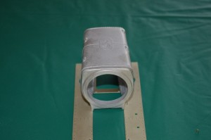 If I took 1.5mm off the inside of each side of the footplate, then the whitemetal cast firebox would no longer fit as intended on the inside edges of the footplate.
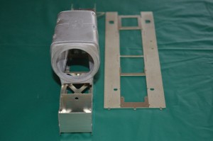
This might not matter, because the firebox would still fit on the frames themselves.
So if I made the inside dimension of the footpale sides nearly the same as the inside dimension of the frames then I thought that it would work. The inside dimension of the frames is 28mm. The inside dimension of the footplate is 26.5mm as supplied.
So if I took 1.0 mm off the inside of the footplate each side, the edges would sit on the middle of the frame each side, which would probably look OK, and the firebox could sit on the frame edges. The only (?!) problem to remain would be that the line of etched rivets on each inside edge of the footplate sits right on top of the line to which I would need to reduce the footplate inner-dimension. Tricky.
So it was tempting to leave the footplate as it is, just cut back the motor-mount. However this would leave the footplate overhanging the inside of the frames, which would not look very good. File the original etched “rivets” flat, then reform them with my special rivet tool?
In all of this, advice from members of the WT forum showed me that I was going to have to cut the motor-mounting back, and reinforce it from within the width of the whitemetal firebox. A slightly daunting task, but eventually I’ve taken the plunge ….. Bitten the bullet ….. etc.
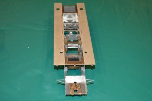 I used some rectangular-section brass to strengthen the motor mount, soldered into place.
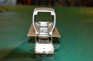 Then I cut off the frame uprights, and part of the motor mount. As can be seen, the footplate can now lie on the frames. Good.
Even better, the firebox goes over the motor mount!
In this view it is possible to see how well this model goes into the ScaleSeven arena: the firebox is exactly the correct width, even though the model was originally intended for Finescale.
Inspecting the footplate now, it becomes clear (see diagram below) that I will only have to shave the 1mm off the inside of the footplate for the length between the two vertical arrows which I have put on the picture.
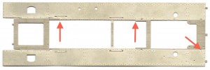 The rest is covered by the parts representing the frames above footplate level.
The angled arrow shows one of the slots into which the parts representing the frames where they are visible above the footplate will fit: just outside of the firebox moulding.
Interestingly, they are exactly 29mm across the outside dimension – as are the frames which I have built.
Of course I shouldn’t be surprised really, but it is reassuring.
