I have now put the steam pipes on and also added the back head and cab roof.
It is beginning to look the part ….

I have now put the steam pipes on and also added the back head and cab roof.
It is beginning to look the part ….
Brake gear.
A problem with all systems where power is picked up from the rails is that brake shoes realistically close to the wheel treads need to be isolated from those on the other side and from the frames, or else short circuits will occur. DC or DCC, I think. Now my system is going to have no pickups from the driving wheels, but the brakeshoes as made in the kit will short-circuit from one side to the other. What options do I have?
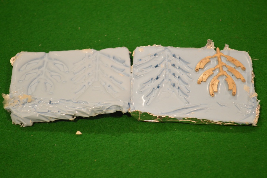
My first thought was to make new brake hangers by acrylic/epoxy molding. So I bought a Sylmasta kit and made molds for the brake hangers for the locomotive and tender.
 I then made castings first in polyester (this was the plastic/resin provided in the molding kit):
These were too friable and brittle, however, so by default I tried molding in Araldite, which was more robust, but full of bubbles:
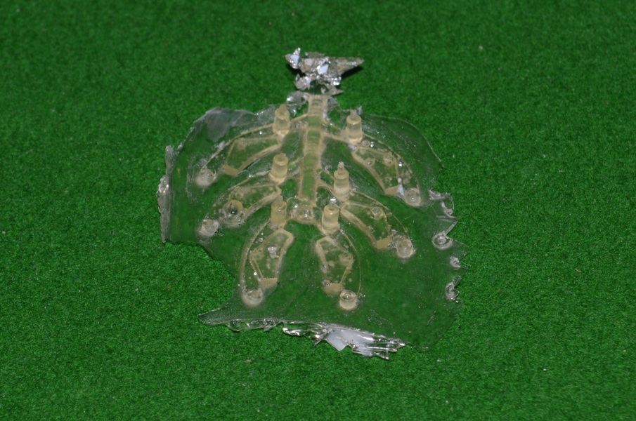
Even these looked unlikely to survive very long in general use, though. Contacting friends for advice suggested that I was trying to make castings of too much: it would be better to make castings of just the brake shoes.
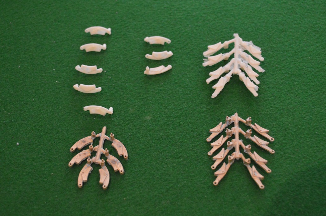
However to do that meant filing all the brake shoes off the hangers (fourteen!) and both making and fitting accurate copies of the shoes onto each hanger. Then it occurred to me – I don’t need to take all the brake shoe off, just the surface which will be in contact with the wheel tread.
So I found some 2mm wide Plastikard strip, and have carefully filed sufficient off the surface of the brake shoes to glue a strip of Plastikard onto each shoe.
So the one on the left has been filed back, and the ones on the right show the Plastikard in place.
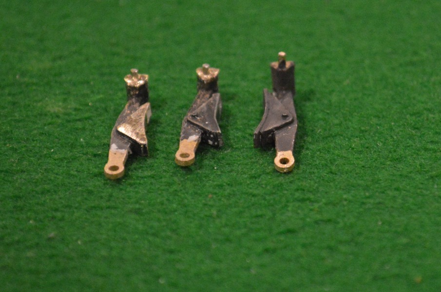
Once I came to try to fit them to the frames the next adjustment became necessary. As the frames are set at nearly the correct prototype width, they are much closer behind the wheels than in Finescale. If the brake hangers are fitted as made, the hangers are too far away from the frames, the shoes are outside the wheel rims and the outside parts of the shoes contact the coupling rods and stop them rotating. So now I became more grateful that the main parts of the brake hangers are metal, not epoxy! The two on the left of the picture above have had the posts from which the hangers are suspended shortened, whilst the right hand one is the original length. I think that this adjustment would have been near-impossible using plastic parts.
Now I just have to fit them, one or two at a time, and make sure the wheels still go round after each fitting.
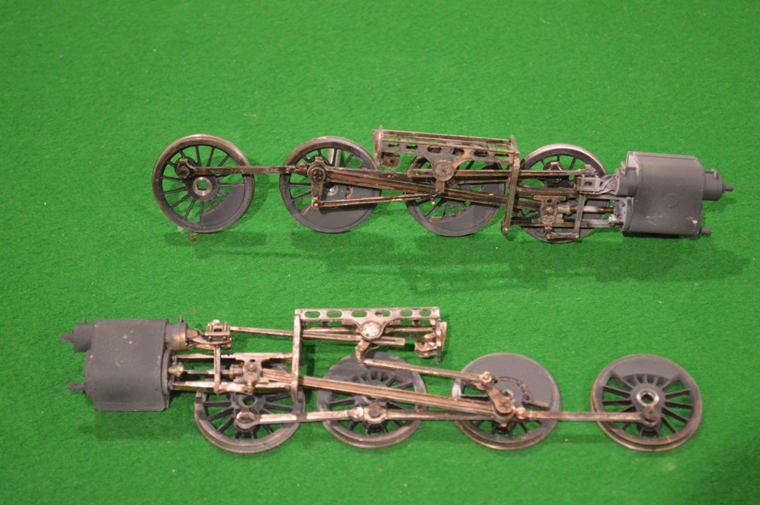
Just an update. Partly because of the difficulty painting behind the driving wheels, and partly because I realised that I needed to put the balance weights on the wheels (and this would probably be much easier if I could lie them flat), I partly dismantled what I had done so far to put together the chassis. Also I realised that the return cranks were on at an exaggerated angle, and although this makes the valve gear move more satisfyingly, I should probably re-do the soldering to make it more realistic (10 degrees is right).
Of course to put the balance weights on is easier said than done. First of all I had to choose exactly which 8F I wanted to model! I found a picture of number (4)8067 which seems to have the right characteristics: a rivetted tender, balance wheels of the earlier type (not all of the weights are crescents) and based in the north of England. So number 8067 it will be.
Both types of weights are supplied in the MOK etches, as pairs (so four of each shape). Using the S7 Group Slaters wheels makes sandwiching the pairs of etches together relatively easy, one on each side of each wheel: the plastic spokes can be cut back a little to accommodate the etches. Not too much on the outer side, though, as the balance weights stand proud of the rims on the pictures I have seen.
 I then filled in the gaps between the etches with Milliput filler.
Now seemed a good time to use Birchwood Casey metal black on the rods and valve gear, to obtain a good “polished steel” finish. I used Hi-Chem “All-Surface Primer” on the wheels (probably only available in Australia, but I’m sure motorcar paint shops anywhere would have a similar product) – it’s a marvellous very thin and very effective metal primer: it sticks to anything, in my experience even glass or granite benchtops! Therein lies a separate story, as you might imagine ….
Finally, a “dirty black’ initial topcoat. My engine is going to have a realistic (I hope) weathered appearance.
So there you are.
David
It’s beginning to look a bit more like an 8F (admittedly I have placed the pony truck in place and the smokebox door just for this picture, though).
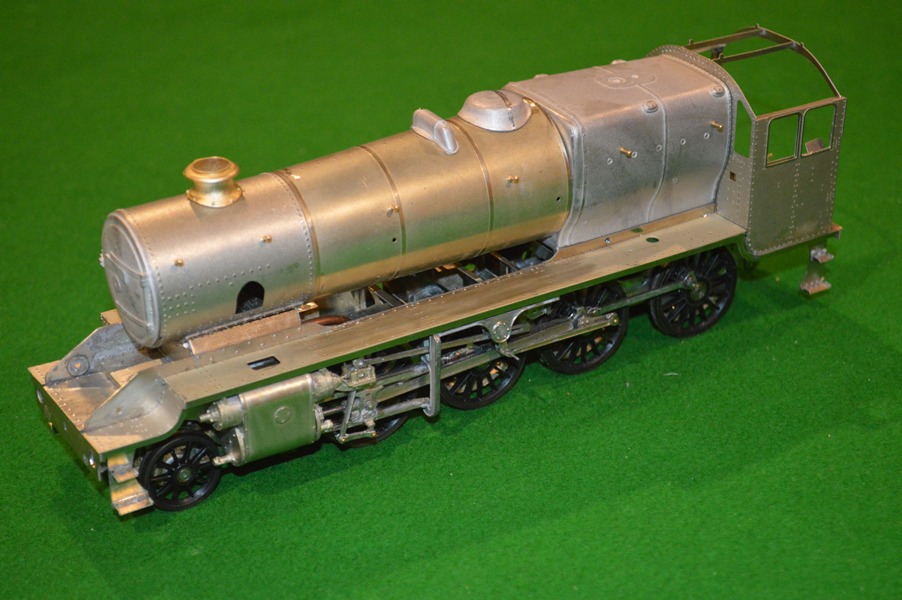 A question however: when I started this project, I saw the picture of a lovely model 8F in brass-and-whitemetal finish. I was looking forward to the day when mine might look similar – but how can that be done if I am also going to have to paint parts of it before I complete construction?
I guess it doesn’t matter really, but if I am to have a realistic painted finish in places like the frames behind the driving wheels, surely this will have to be done by taking the wheels off. Especially if I wish to have a good finish on parts like the springs, which are right behind the wheels, of course. As you’ll observe from the above picture, I haven’t put the braking gear in place yet. Once I have done that the wheels will be very difficult to take off. At present the wheels can be removed easily, because the excellent design of the MOK kit allows the motion bracket, valve gear and wheels to be removed as a unit.
 So, how do other modellers manage it?
How do you make a whole brass-and-whitemetal kit up, and later get a good finish on it, without giving yourself a huge amount of unnecessary work dismantling all the careful modelling done to put it together in the first place?
Answer (I think): you cannot. On the ‘net are articles describing how people have made up a model completely, then have to spend lots of effort systematically pulling them apart so that they can then be painted! When it comes down to doing that, I do not think pictures of the unpainted model are so important, so I will paint the frames behind the wheels at this stage (and probably most of the stuff in-between the frames also).
 First stage, take the wheels and the motion off the frames. Fortunately this doesn’t prove too difficult.
This will also give the advantage that I can put the balance weights on the wheels whilst they are flat on the desk, rather than mounted on the frames.
 The frames themselves will be easy to paint I hope, although I will have to mask off the sliding hornblocks (bearings) for the driving wheels, and avoid painting the compensation mechanism on the insides of the frames.
The balance weights will have to be chosen. I hadn’t realised, but there are many variable configurations of balance weights between difference individual locomotive which are otherwise indistinguishable. So I will need to find a picture of a locomotive in the area where I want to model (not too important) with a rivetted tender (which I think looks nicer), and then try to match the available parts from my kit to make the appropriate balance weights on my locomotive. So, where do I find a side-on view of a Stanier 8F, pulling a tender with lots of rivets on the side, on the Settle-Carlisle Railway (or, at a pinch, anywhere in Lancashire or the North-West?
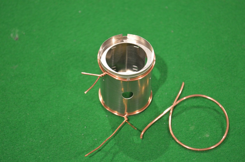 Having the formers to make the accurate cylinder was useful as well. This picture shows the copper wire (from mains electricity cable) used to squeeze the inner cylinder of nickel-silver down onto the formers. Thicker copper to hold it in place, then thinner copper to squeeze the metal down.
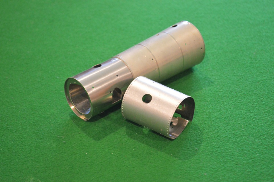 After that it was easy (relatively) and both the smokebox and the taper-boiler could be made accurately.
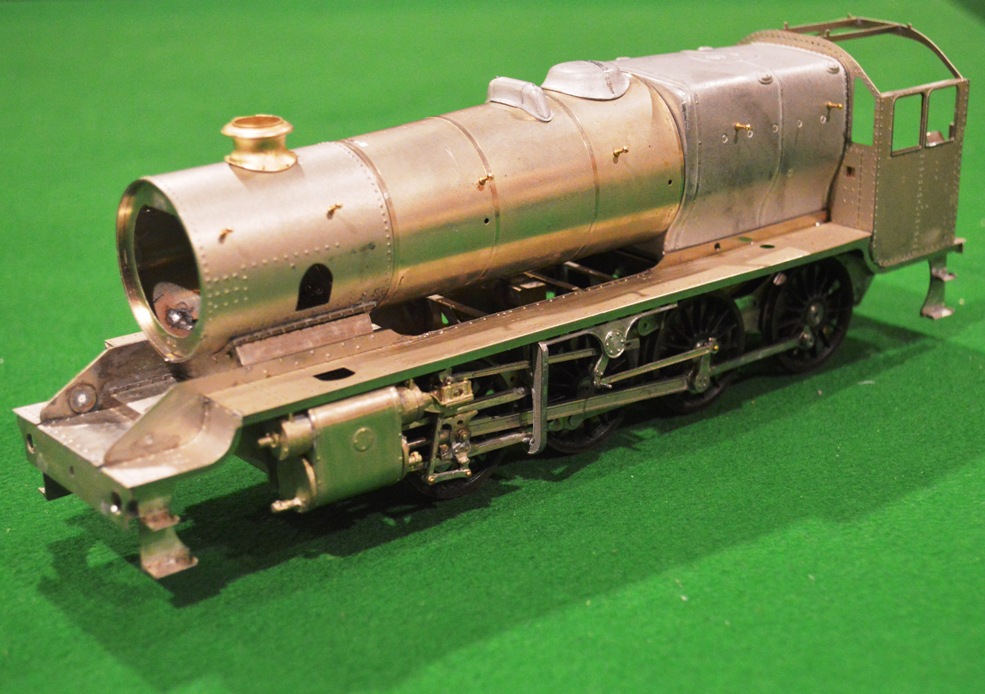
The 8F is progressing well, and I have been able to fit the special parts and run the assembled chassis for the first time!
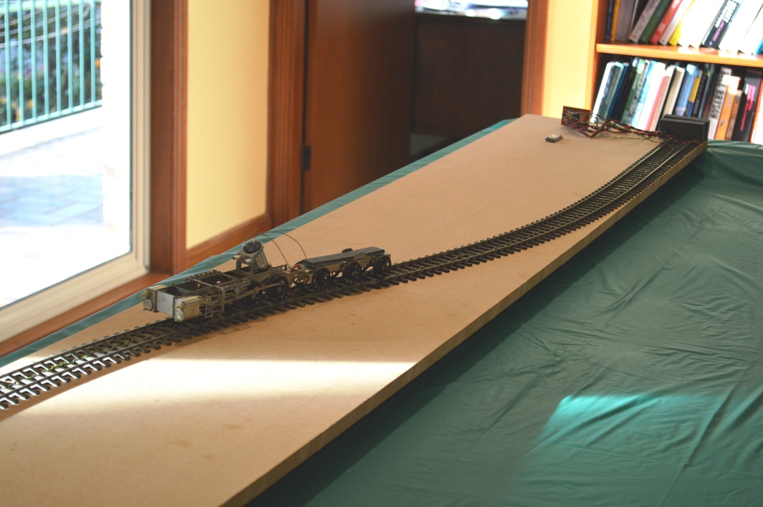
It was a great moment to see it move for the first time. After I cleaned my test track, it ran for the first time with almost no hesitation.
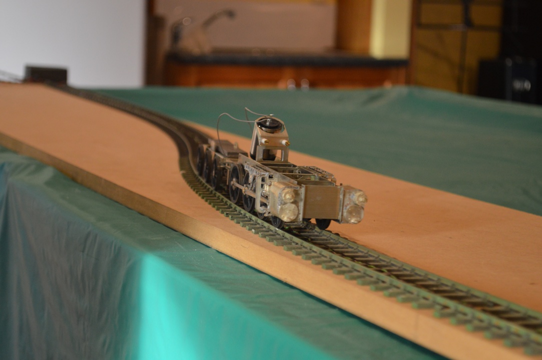
I decided to try running it with the connecting rods in place but before I try the return cranks, etc. I had to wait to try out the running until the tender pickups were done.
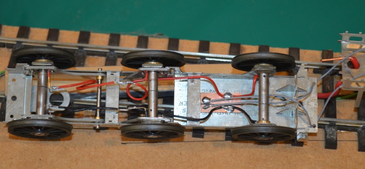
The third picture shows the tender pickups: the compensation mechanism is still able to work (I have left loops in the wires to allow this, but there’s still a lot of gear to go into those spaces, so I’m not sure how well this will work) and the temporary connections visible going to the loco. chassis on the right. The split axles can be seen.
It doesn’t look much like an 8F, and the motion isn’t all connected yet but it shows that the tender pickups are working and that the assembly so far is acceptable.
It runs better forwards than reverse at the moment, but goes reasonably smoothly at 7V drawing 100-200 mA, and it’s still running without any lubrication.
I have started on some of the bodywork for the tender. For someone like me, this threw up some significant difficulties due to my lack of expertise: how to bend the top edge of the tender sides? I have bent sheet metal before, to make the Belpaire firebox of my industrial Garratt, but this was brass, and not a particularly wide sheet of metal, either. The nickel-silver sheet for the tender side requires an even bend along a length of about 11cm. Dave Sharp from MOK has instruction about how to do it, but they are sketchy. The bend covers a height of about 3.5mm in the side, so I worked out that as the bend was through about 45 degrees, a bend of about 8mm diameter would be about right [8×3.5=28mm, divided by Pi = approx. 8mm diameter].
 The instructions show how to draw lines on drafting tape inside the bend, to position it accurately. This is good, but how to make the bend? My first try was to place a slightly smaller diameter drill to bend around, and clamp the tender side in my big vice.
However I simply couldn’t bend the nickel silver!
In any case, the drill wasn’t really long enough, and the ends might not bend properly. I was talking/e-mailing Richard at the time, and he suggested I buy a longer rod, of slightly smaller diameter than the bend I wanted to make, and then either roll the sheet over the rod using a rigid metal plate to transmit even pressure, or clamp the top edge of the tender side in the vice and bend the body over the bar. I suppose it was a little foolish of me to try to do it the other way around, but somehow it seemed right to bend the bit that is supposed to be bent, rather than bending the body down whilst holding the part which is supposed to be bent, upright in the vice!
I started to try to bend the sheet over a piece of 1/4 inch (6.3mm) aluminium rod which I found, on our granite kitchen benchtop (the household manager was out), but it was very difficult to bend, and also I thought that this technique might not produce a discrete bend in the flat sheet of the tender side (if you see what I mean), but rather make it a nice continuous curve in the metal sheet. It was impossible to hold the rod still relative to the sheet metal whilst trying to make the bend.
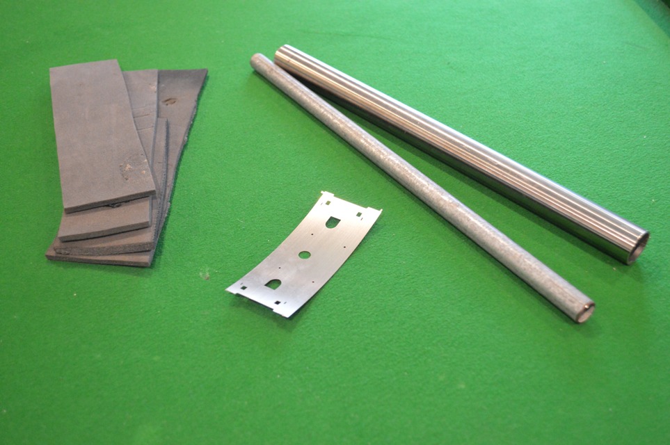
 So, back to the vice. The trouble now was to hold everything at once, to allow the rod and the tender side to be exactly positioned. So I used masking tape to hold the rod against the aluminium angle used to make smooth jaws in my big bench vice, as shown on the left.

Then I put the tender sides into the vice and could adjust the position so that the start of the curve was held in between the rod and the vice, the other end of the curve being above this (in the picture one can just make out the second line):
This finally allowed me enough leverage, using a thick rigid steel rule, to make the bend in the tender sides.

 It also allowed me, using the same technique, to form the vertical curves at the front of the tender sides (a bit out-of-focus in the picture, sorry).
HAPPINESS !
David
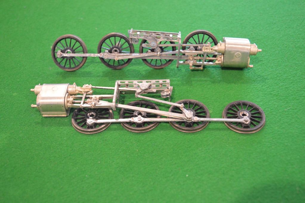
 The Slaters Wheelset has arrived, and very nice it looks too.

Coupling rods (articulated as shown), crankpins and crankpin bush
They come with an innovation (to me) from Slaters: crankpins which can be screwed into a boss set on the crank.
However  for wheels on an S7 version of the MOK kit, they create a problem, illustrated in this picture:
The crankpins are clearly too long in this case, and their rotation will be obstructed by the crosshead and slidebars.
Now I am familiar with this problem from when I widened the frames and cylinders, etc., for my S7 Industrial Garratt, and actually this doesn’t look quite as bad as that one did. However I will need to shorten the special crankpins made by Slaters (if you look closely I will need to cut them back to move a bit more that the threaded part of the pin), and then I will need somehow to reproduce a thread on the end of what remains.
With the old Slaters system it would have been easy, but here the crankins are completely different. The part threaded to go into the boss in the wheel is 10BA. The smooth part of the pin, to go inside the coupling rod and connecting rod bushes) is also 1.6mm O/D, but the retaining nut screw-thread is 12BA.
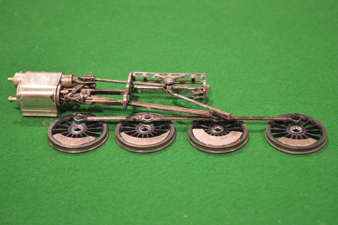
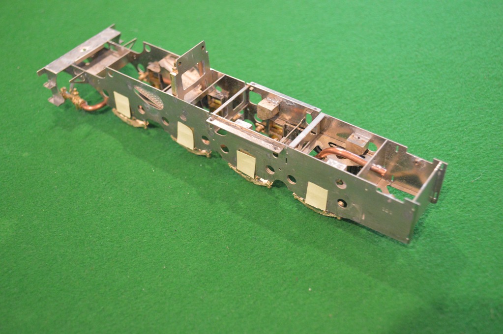
After seeking help from the experts/enthusiasts on the WesternThunder website, below is my first plan [I suspect that this is destined only to be the first plan]. The picture shows the frames with wheels in place. The front end is on the left. I am going to take advantage of the special construction of the S7 wheels, with the 10BA tapped holes for the crankpins.

I am lucky in having my friend in Melbourne Richard Davidson who has done some work on his lathe for me. Below the frames in the picture are the special crankpins which Richard has made for me.
My illustration shows how I hope to arrange the crankpins. From the front: axles one and two have the special crankpins in place. Axle one the pin is part-way through the coupling rod. Axle two has the crankpin all the way home. Axle three and four have the Slaters crankpins. The ones for the connecting rod wheels are longer, and will take two brass bushes on top of each other, through the coupling and connecting rods. The final axle will have a standard Slaters crankpin and bush.
Clearances will remain extremely tight at the front end. I intend to try the front crankpin fitting direct to the wheel without a washer. The boss on the coupling rod is slightly thicker than the body of the rod itself, so as it goes round it should be clear of the central wheel boss. The second wheel will need a washer, though: the articulation of the coupling rod will catch on the central wheel boss otherwise. By the third axle, fortunately, the clearances should be less critical. So the flat portion of the Slaters crankpin, acting as a washer, will be less critical.
I hope that it all works …..
Following on from part 6, I found out from MOK (Dave Sharp) that I had definitely put the base of the cab on upside down. This has all sorts of minor but annoying effects. One was the fact that the formers inside the base of the cab had been made to accommodate the etched plates which were meant to go inside the curved sections (making them invisible – they are there only to make curving these areas easier). So the formers made the curved plates have a larger diameter of curve – hence leaving a gap at the outer end: exactly where I had found one.
 After much debate inside myself, I decided that I would never be happy if I did not do the job properly, so I pulled all the cab base apart using a 75 Watt soldering iron. Once back to the component parts I tried to clean all the solder off the nickel-silver, then I flattened the bottom plate completely (apart from the front plate [see below]) first with my fingers, then with
 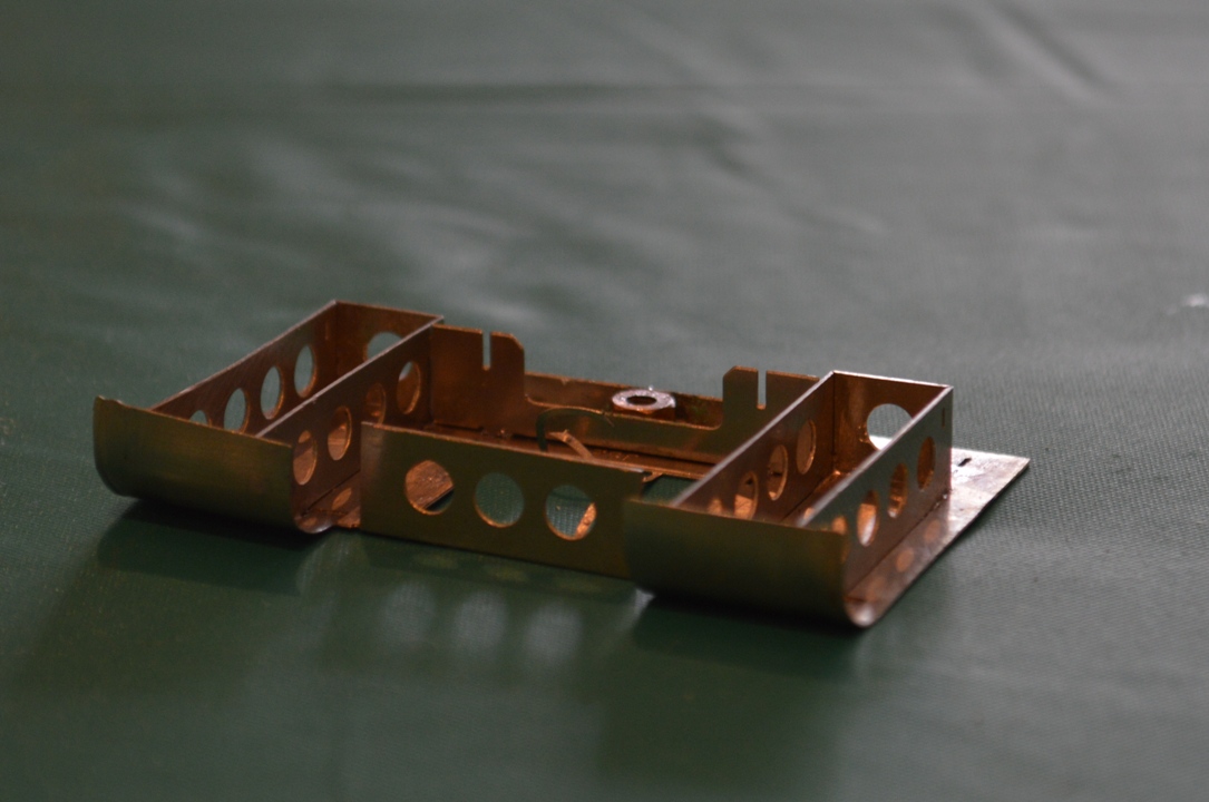 a tap hammer on a piece of flat granite. The front plate (with three holes) is now bent upwards as it should be.
I then reformed the curves, fitted the formers back (now easier because the former correctly fitted onto the curved sections. At the point shown in the picture, my soldering iron stopped working. So I have sent off for a replacement.
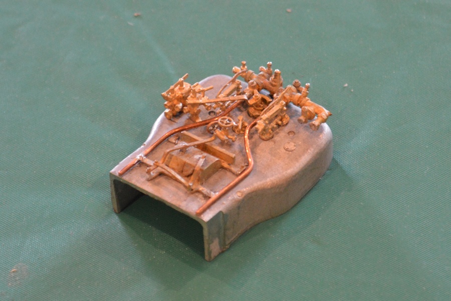
Whilst I wait for a new 25 Watt soldering iron, here is a picture of the completed boiler backhead.
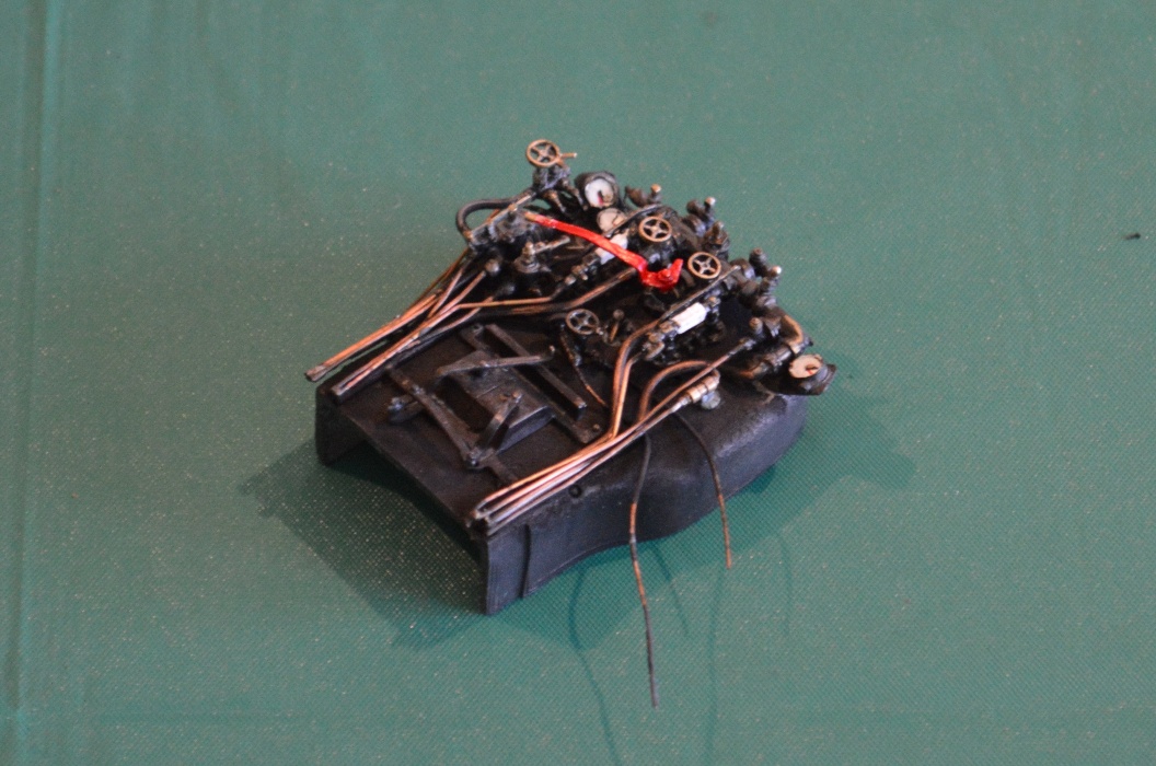 I am quite pleased with it. Basically I followed what fittings I could see on photo.s of preserved and other engines, and then upt as many pipes as I could on the brass castings, to be realistic. I “painted” it using metal blackener, scraped some off the copper pipes and painted the dials and water gauges by hand. A thin covering of matt varnish to complete the work.
I may have made a mistake, which has exposed a difficulty/problem with the etches, not related to ScaleSeven however.
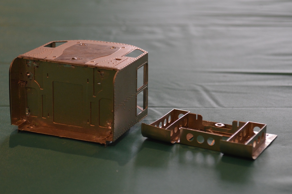
The first picture shows the overall basic construction of the cab: there is an undefloor part which I guess if faithful to the protoytpe, but is completely hidden one the parts are put together!
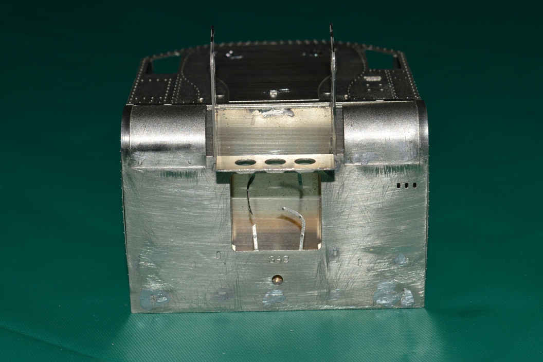 On the underneath of the cab is part no 362, which is curved upward to make the curved plates leading up to the footplate.
This shows that I may have put part number 362 on the wrong way up. I am guessing this because the three holes to take the damper levers have ended up on the wrong side. However putting it the other way up would mean that the fold for the panel at the front with three round gaps in it would be on the wrong side to bend it downwards – ie the bend would be away from the etched line. This is why I used it the way up which you can see in my pictures. Also the half-etched areas at the front on the curved plates I thought must be on the outside, because otherwise they would be completely hidden!
 So, if my analysis is correct, either the three holes for the damper levers are on the wrong side, or the etched line to fold the front plate is on the wrong side.
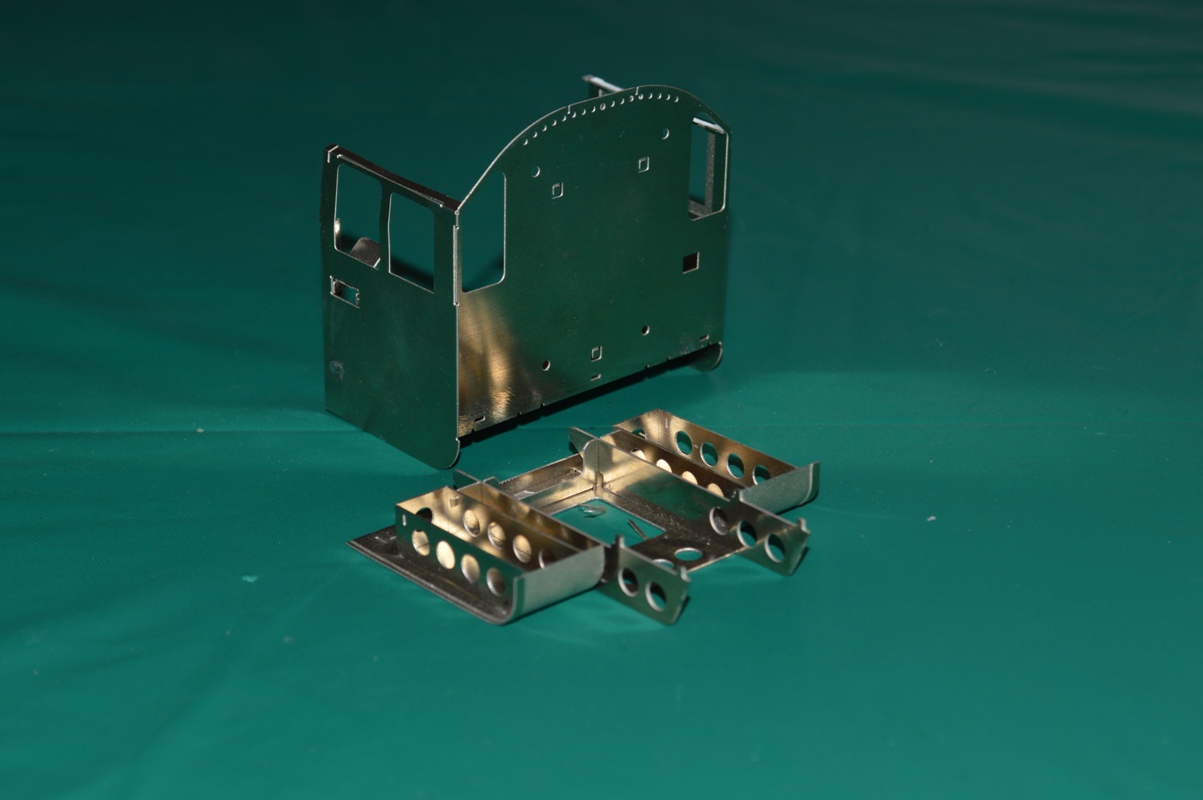
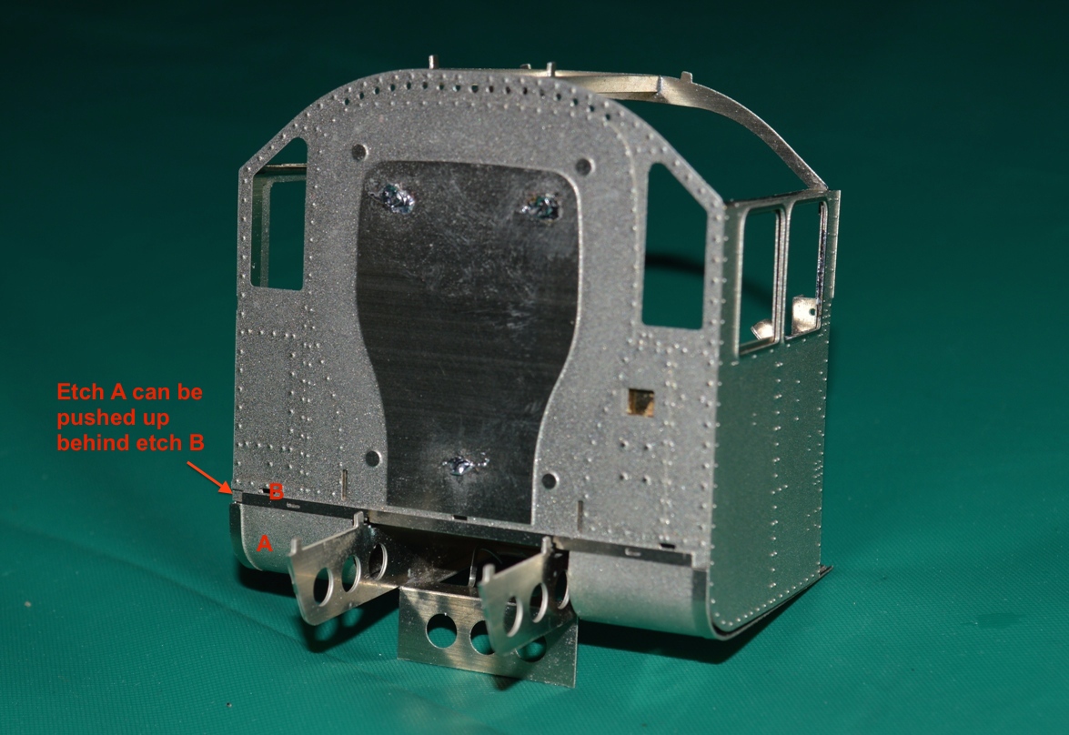
If you look at picture No.s 3 and 4, you can see that despite my care I have ended up with a gap between the cab-side etches and the curved part 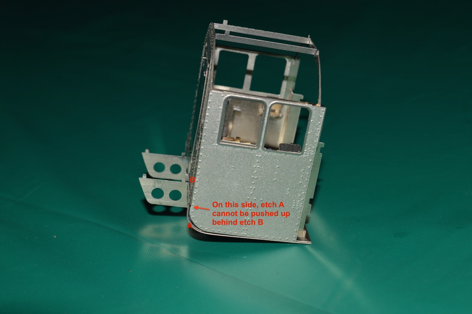 of part number 362.
On the right side this doesn’t matter, because if I push the curved part upwards, it neatly fits behind etch number 367 (this is the front of the cab, immediately behind the whitemetal firebox I think). This allows the shiny (unetched) strip at the side of the curved part on 362 to line up with the shiny strip along the lower edge of part number 367. Fine, it looks made to do just that. There will then be no gap along the bottom of the cab-side etch. The trouble is that on the left side, the curved part on 362 just abuts the thicker edge of part number 367 rather than going behind it, and leaves the curved part on 362 with a gap between that and the cab-side etch. This could be cured by removing a mm from the upper edge of part 362, but I’m reluctant to do that without knowing that it really needs to be done. Also with the assembly done so far, it will be awkward to do. However advice from the Scale Seven fraternity on the Western Thunder website suggests that I have put the base on upside-down and the removing a mm from the curved part is therefore exactly what I will have to do.
While I wait for the S7 wheels (for them to be sent to Aus., I want the whole lot at once, and I gather Slaters haven’t produced the pony truck wheels yet, although the others are ready), I have also been putting the details on the backhead.
It looks good so far, but it has been difficult to identify exactly where all the tiny lost-wax castings go.
I need to find views of the inside of an 8F cab, showing the backhead. The “Locomotive Profiles” books have two, but one is of an oil-burner, and the other one doesn’t seem to have the same components as provided in my kit. Mostly it is the same, but some parts are seemingly missing from the kit (the one described in the book as the “independent steam valve”), and doesn’t appear to be a casting either for the “blowdown valve” or one which goes where the steam sanding valve should fit, between the left water glass and the brake handle. There is a casting which can be seen in my picture placed in position, but if fixed there it will obstruct the regulator handle.
The pictures that I found via Google images didn’t help. Again I have turned to the WT website for help, and I am a little closer to answering my questions now. Later versions of the 8F don’t have the sand gun control valves in the centre of the backhead, and there are some other little details which I will have to change.
More pictures when it is done ….