Stanier 8F in Scale Seven Part 31 – Running on the Layout

It has taken a long time, and I have had to re-lay some of the track, but I can finally show the model Stanier 8F locomotive pulling a fairly long train of coal wagon around my model of a colliery.

This shows my 7mm scale, Scale-Seven, model of a Stanier 8F 2-8-0 freight locomotive running around my model colliery.  The track is a bit rough, and I had to relay some of it to allow the eight-coupled (long fixed wheelbase) locomotive to go around the curves, and up and down the gradients I have made in the model.

In fact at the moment, I can make the engine and wagons go around the loop in an anti-clockwise direction, but if I try to have it run around clockwise, it comes off the rails!

However I suspect that the problem is with the track work, rather than the engine which I made.


Stanier 8F in ScaleSeven – Part 29

It may not be to everyone’s taste or interest, but my ‘blog about building this kit has entertained me and John, at least!  It is very much the same as some entries which I have made on the Western Thunder website <http://box5457.temp.domains/~coulshed/australian-family-events/>, but that one is for seriously train-autistic people (joke  ……..)

Small Black with numbers 2Even at this stage there are mistakes to be made, and lessons to learn, perhaps.

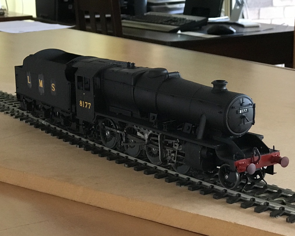
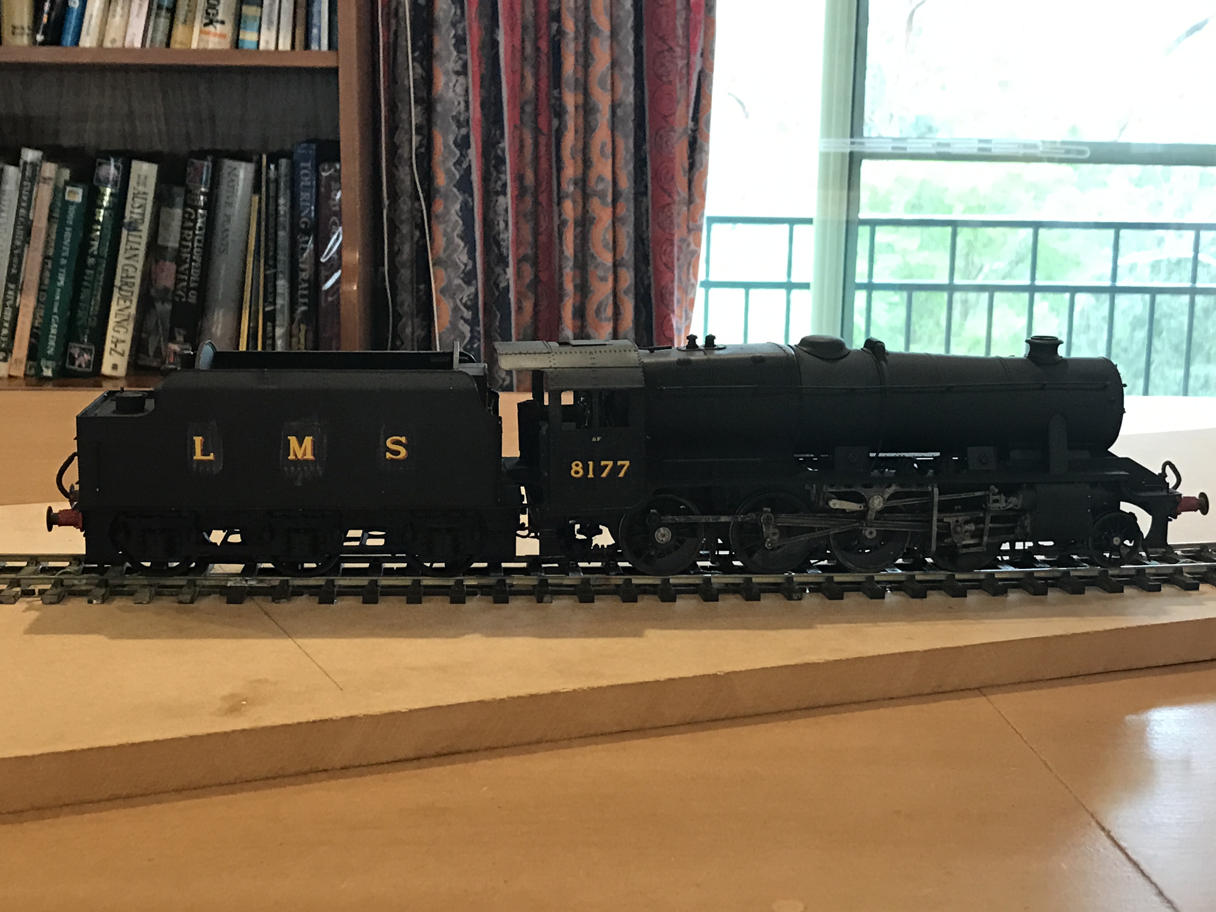
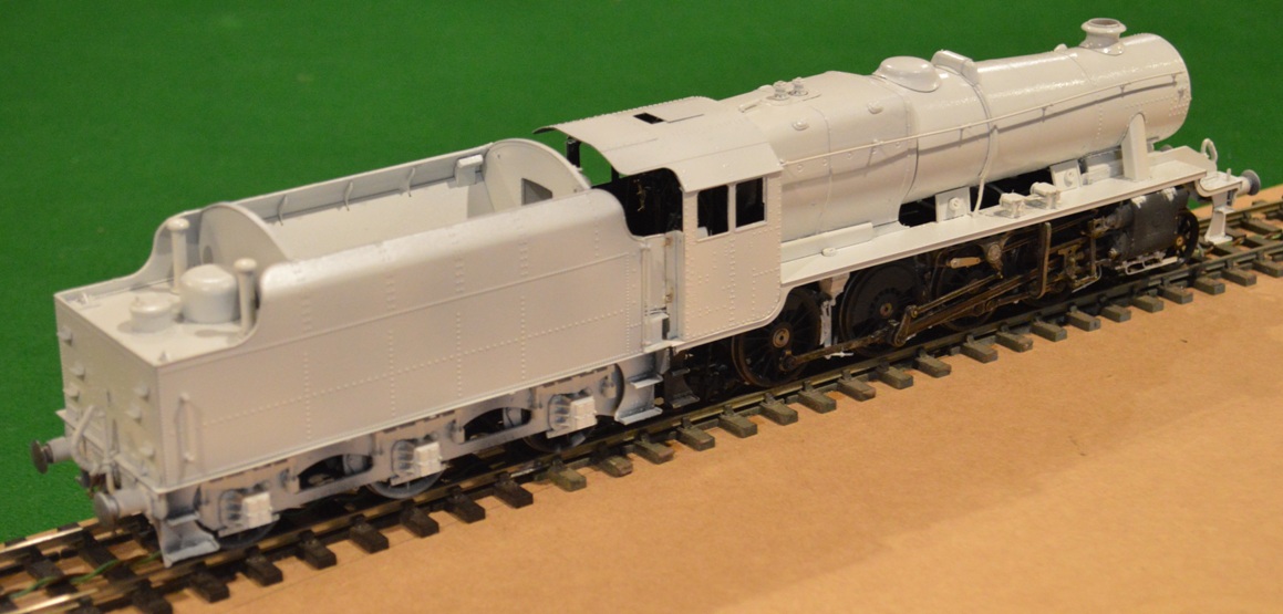
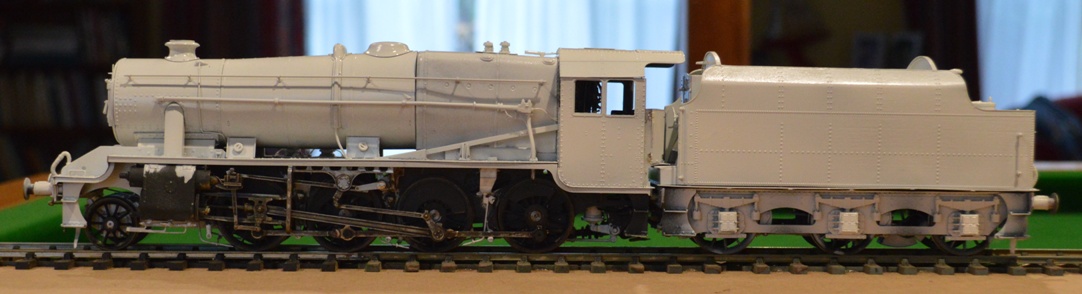
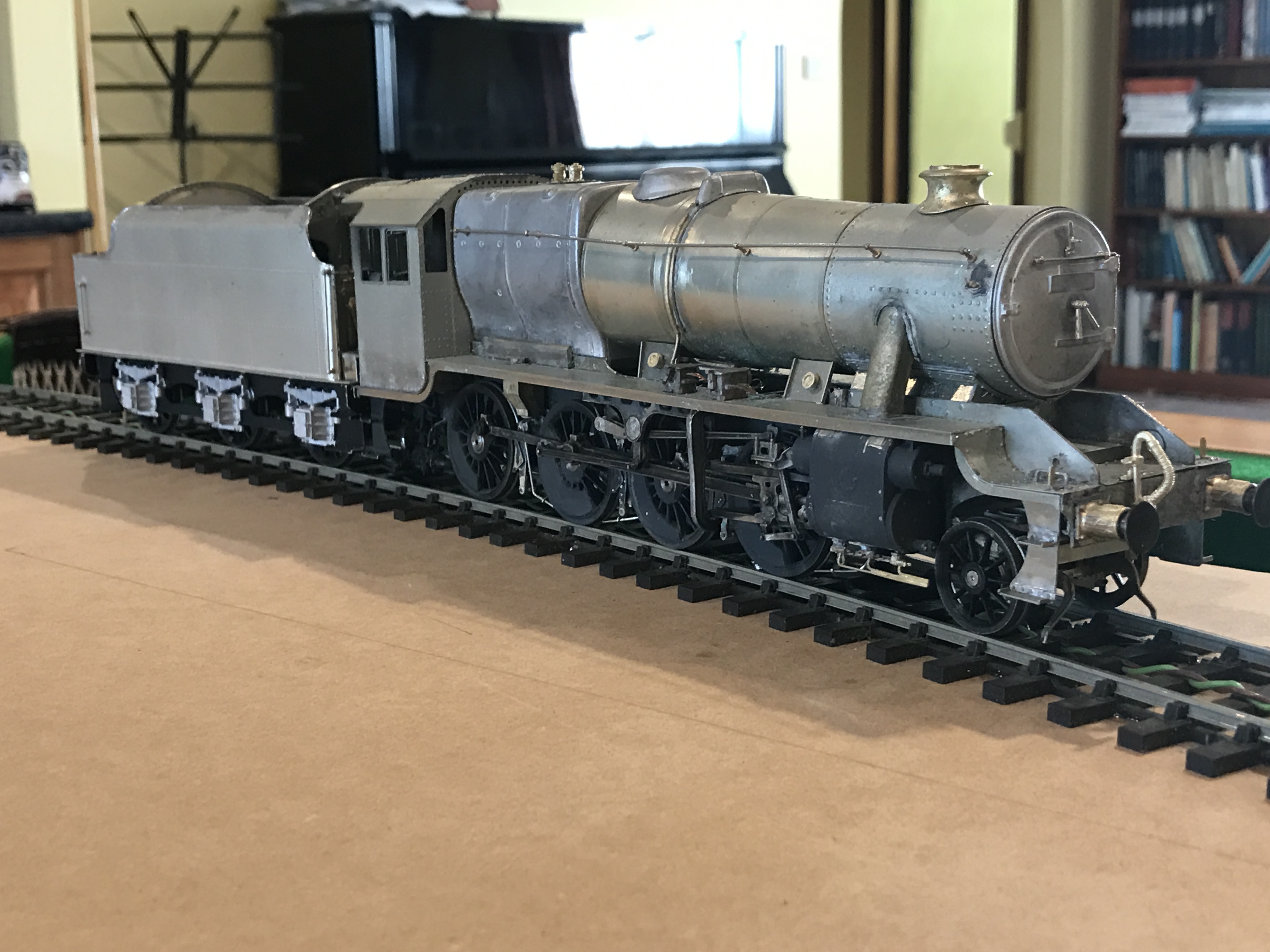
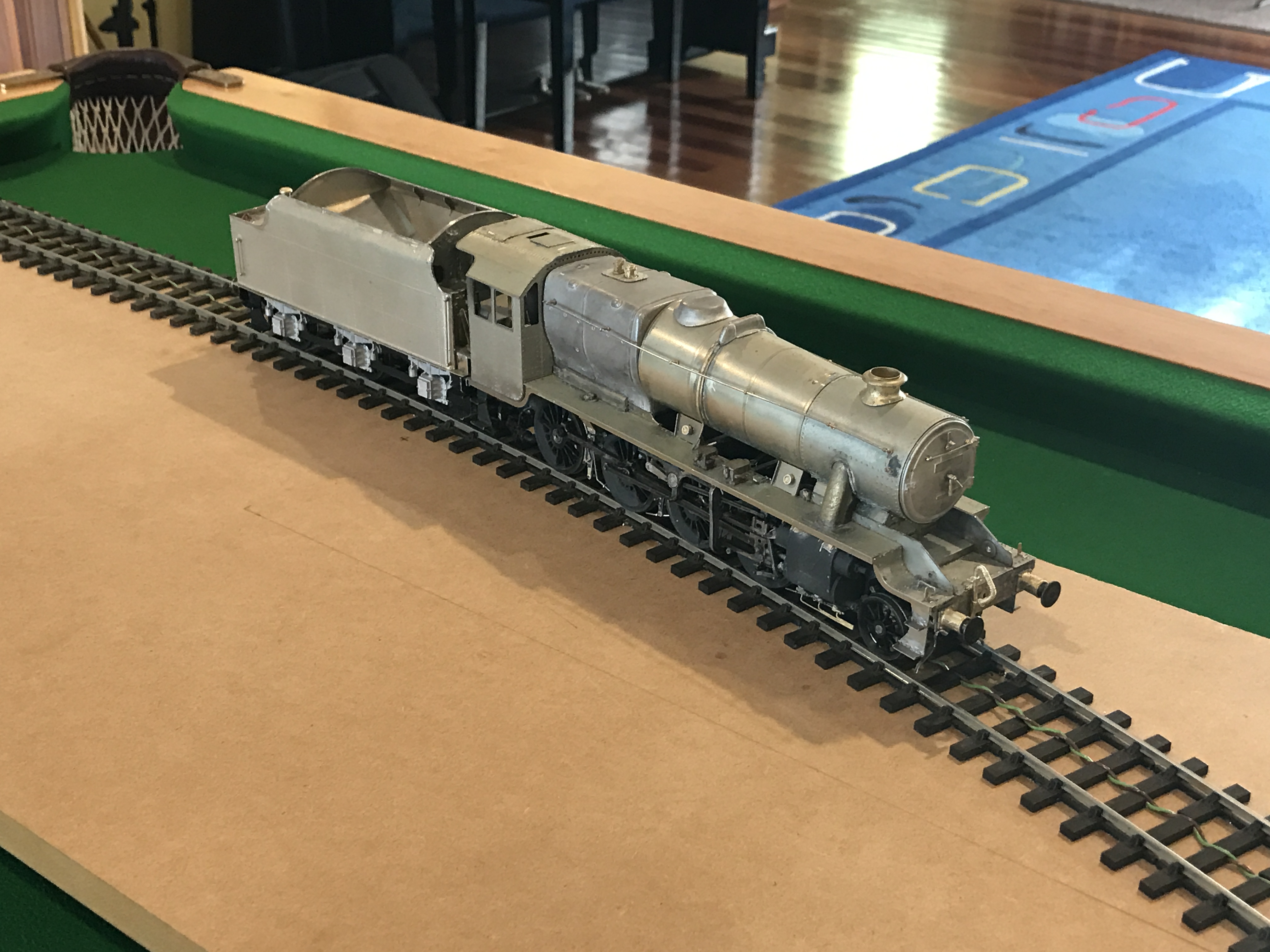
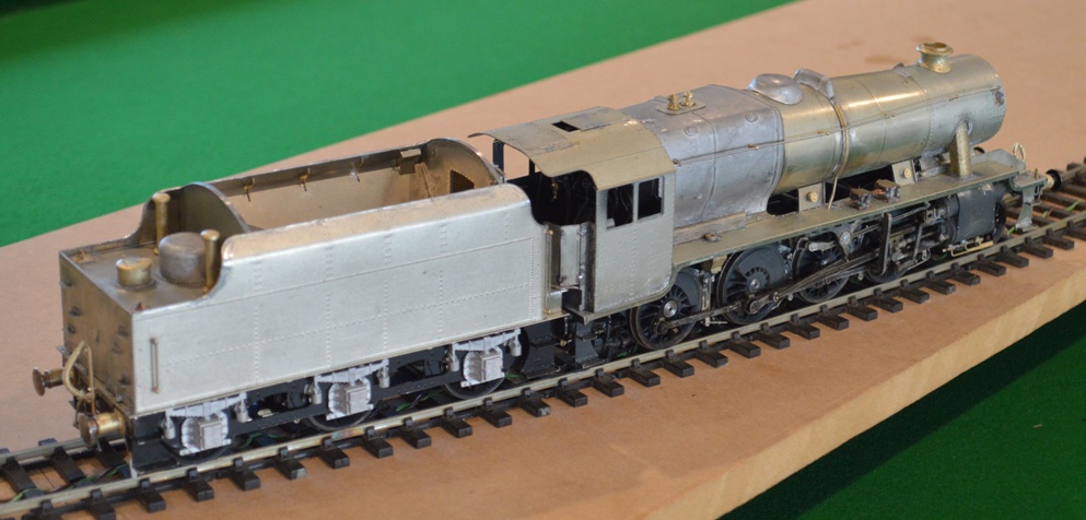
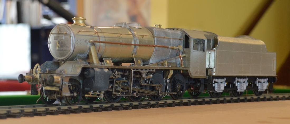
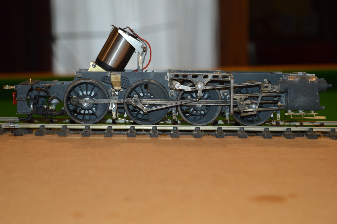
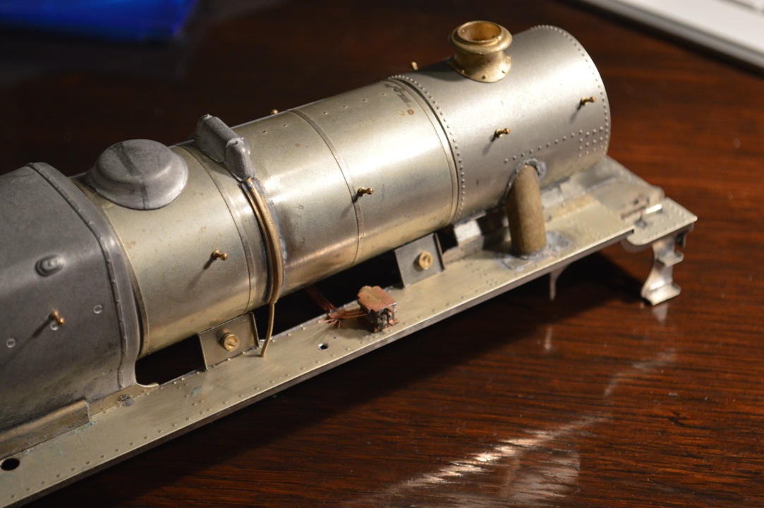
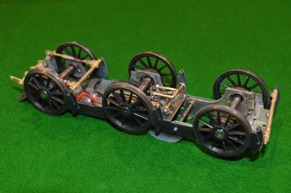
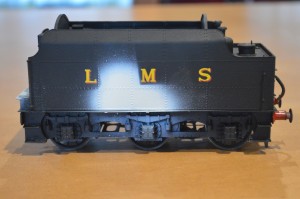
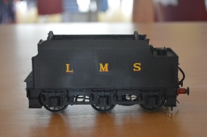
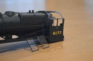
For those who see these things there are several problems with the  locomotive as seen here.
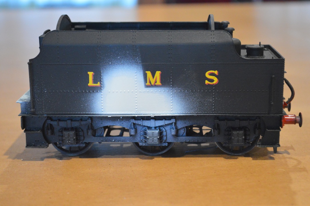
Most obvious is the water-based varnish covering the letters and numbers.  Perhaps less obvious is the lack of window-glass.  Least obvious (perhaps) is the fact that the central two pairs of driving wheels in the second picture are not exactly on the rails ….

In order.
I have had trouble with solvent-based varnish destroying transfers in the past, so once my transfers were in place I fixed them with water-based matt varnish, with the results shown in the pictures. This in itself I did not see as too much of a problem, because I thought that once an airbrush-applied coat was put on, the streaking would vanish.
My mistake, though, was to use a short-cut and (thinking that the varnish already there would protect the transfers) I used a “Testors” aerosol “Dullcote” varnish on the tender sides.  Whilst the transfers survived, it produced bubbles and wrinkles in some of the plain paintwork!

Small Late corrections 02
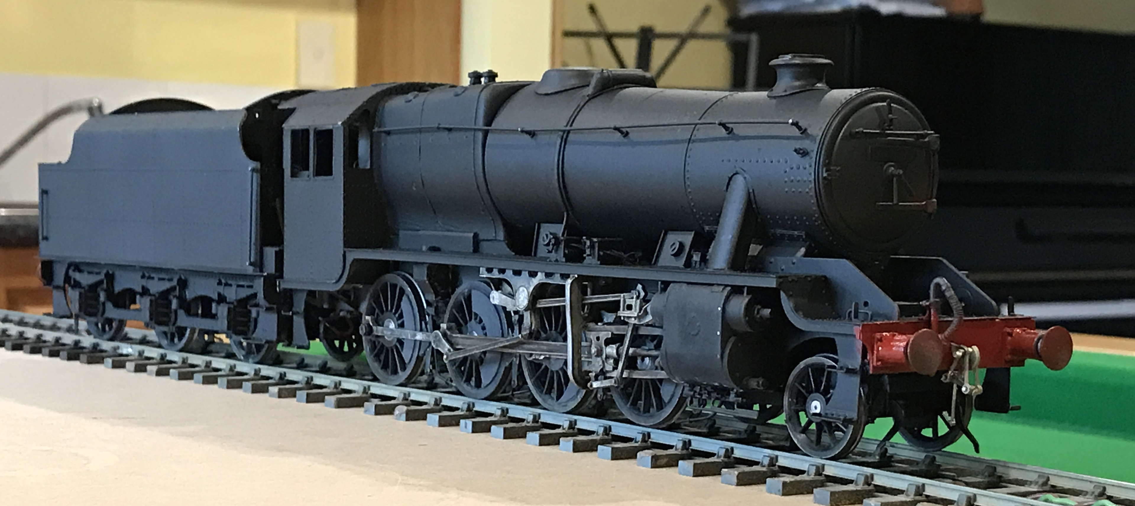
Disaster. They were large enough patches that, even allowing for my intention to produce a weathered appearance, I couldn’t leave them as they were. I didn’t want to have to do the whole sides all over again, so rubbed off the sections of affected paintwork with a glass fibre brush, back to bare metal, then resprayed with primer, masking the letterwork.

Small Late corrections 04Then I resprayed with matt black.


It isn’t perfect by any means, but after weathering I don’t think the differences will be visible.


Next the windows.

Small Late corrections 01
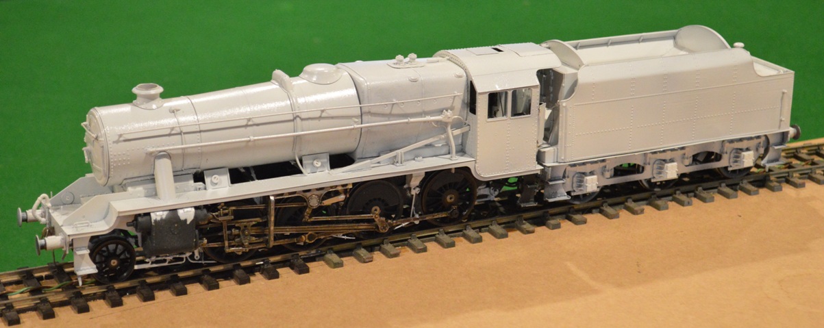
Initially I wanted to use microscope coverslips to make real glass windows, and even bought a tungsten scriber to cut the glass.  However I soon realised that the coverslips were incredibly fragile, and I thought that in my hands would soon be broken in place on the loco., when replacement would be very difficult. Also I realised that there was no way to produce the front-facing windows on the cab from glass, anyway. Whatever method I used, I realised that the front windows were going to be impossible to position without taking the cab roof off. So rip it off I had to do (well, carefully unsolder and lift it off ….).
Using plastic “glass” was OK until I was unwise/uneducated enough to use cyanoacrylate to glue the side window frames in place. Araldite had been fine to secure the plastic sheet to the frames, but cyanoacrylate has made some of the glass go “misty”. Well, I suppose there may have been quite a bit of steam in the cab at times ….

Finally the problem with the wheels.
Once again, this is probably something a more experience model-builder would have avoided, but bear in mind that this is the first tender engine kit that I have ever made – three tank engines and a Garratt before this.
Small Late corrections 03


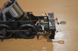
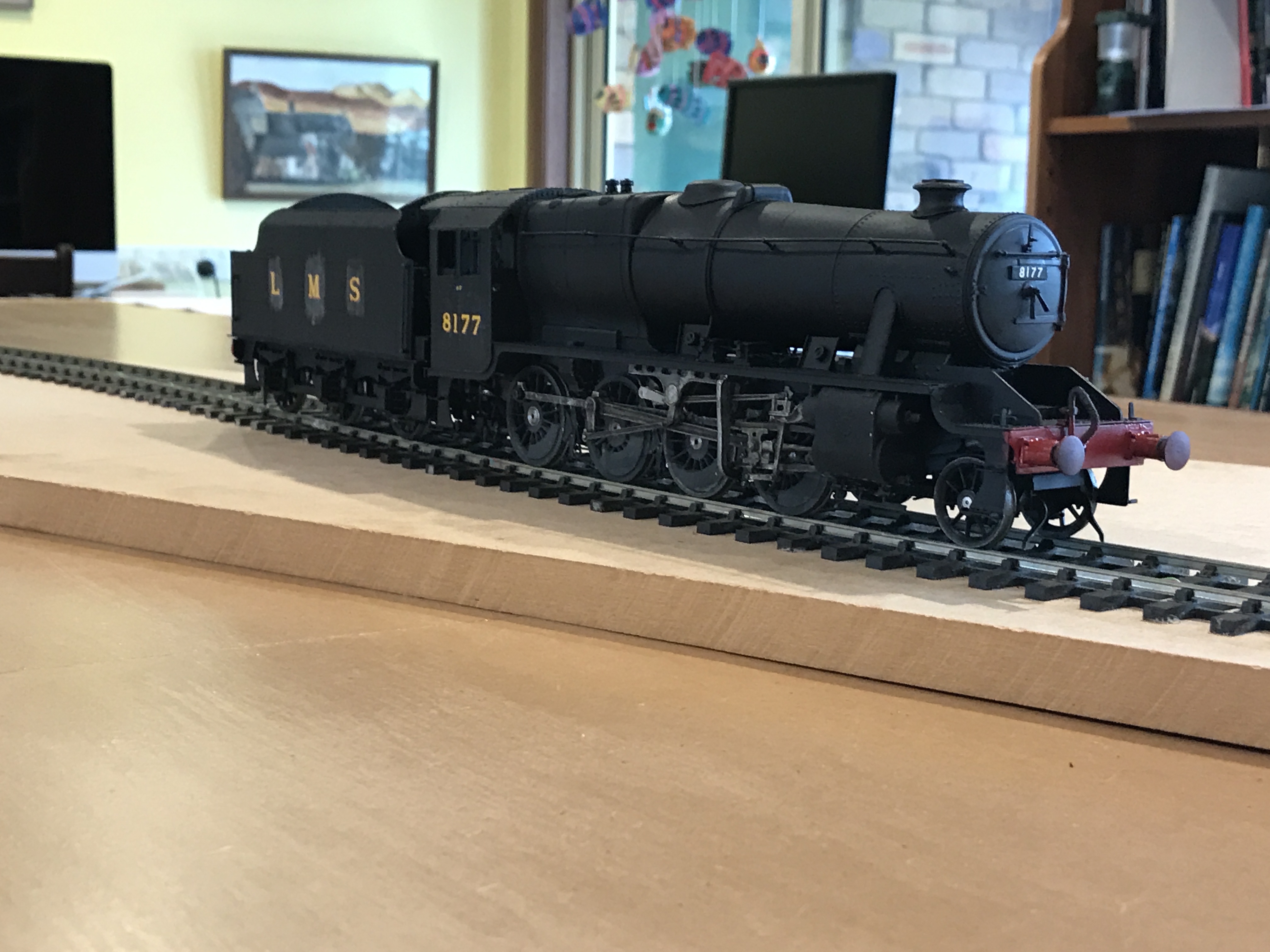
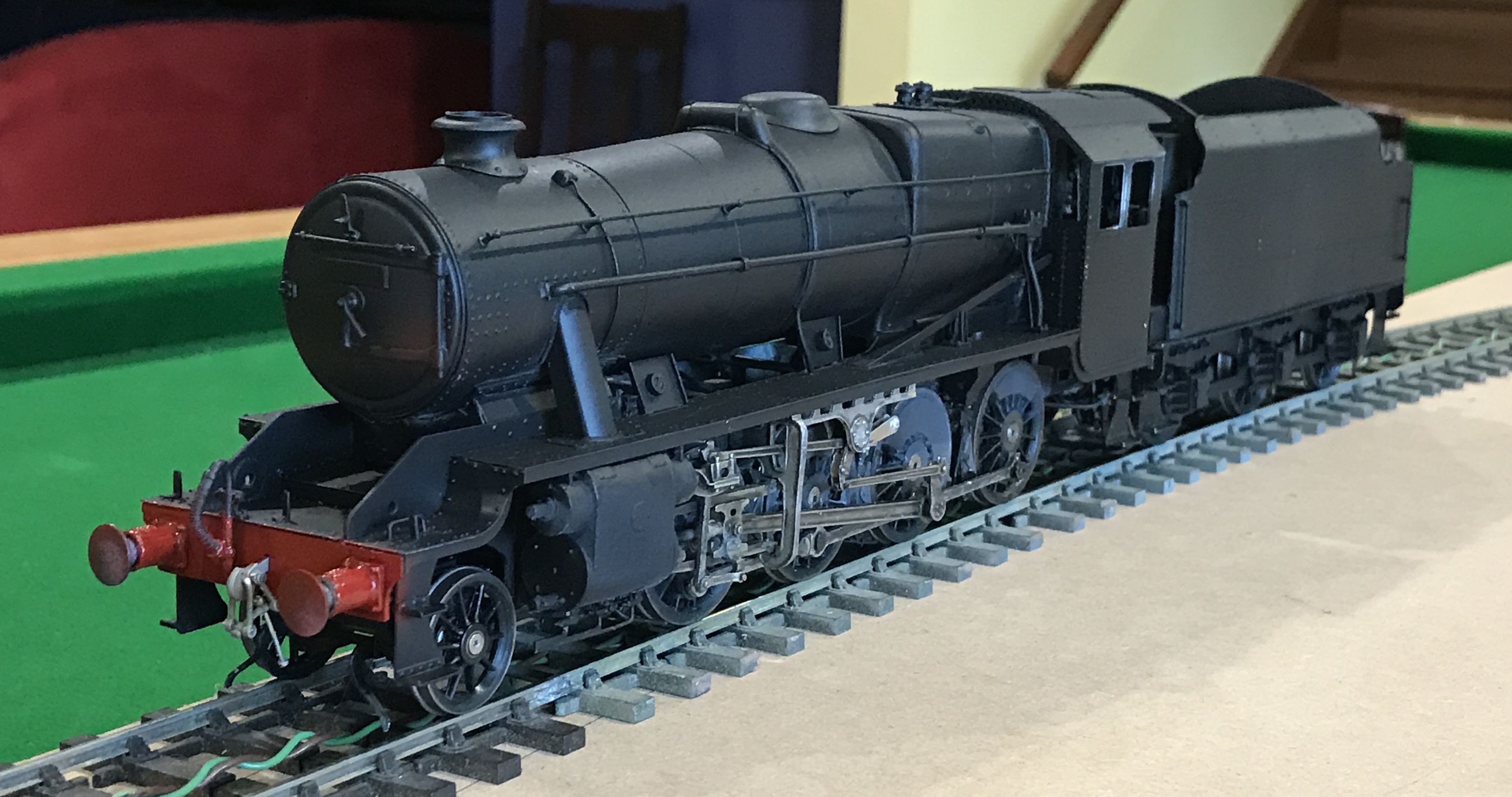
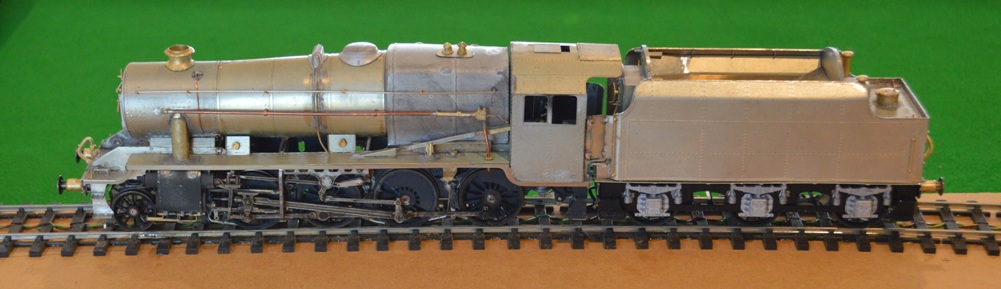
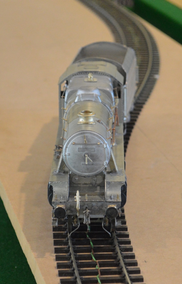
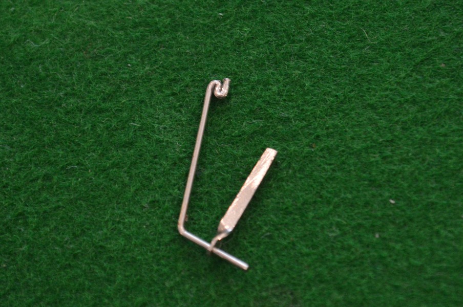
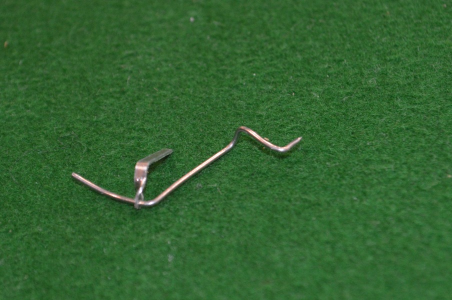
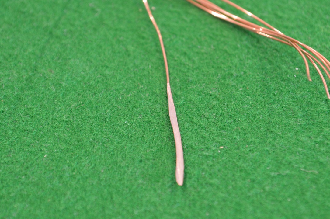
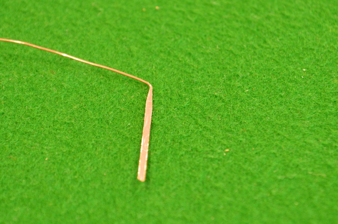
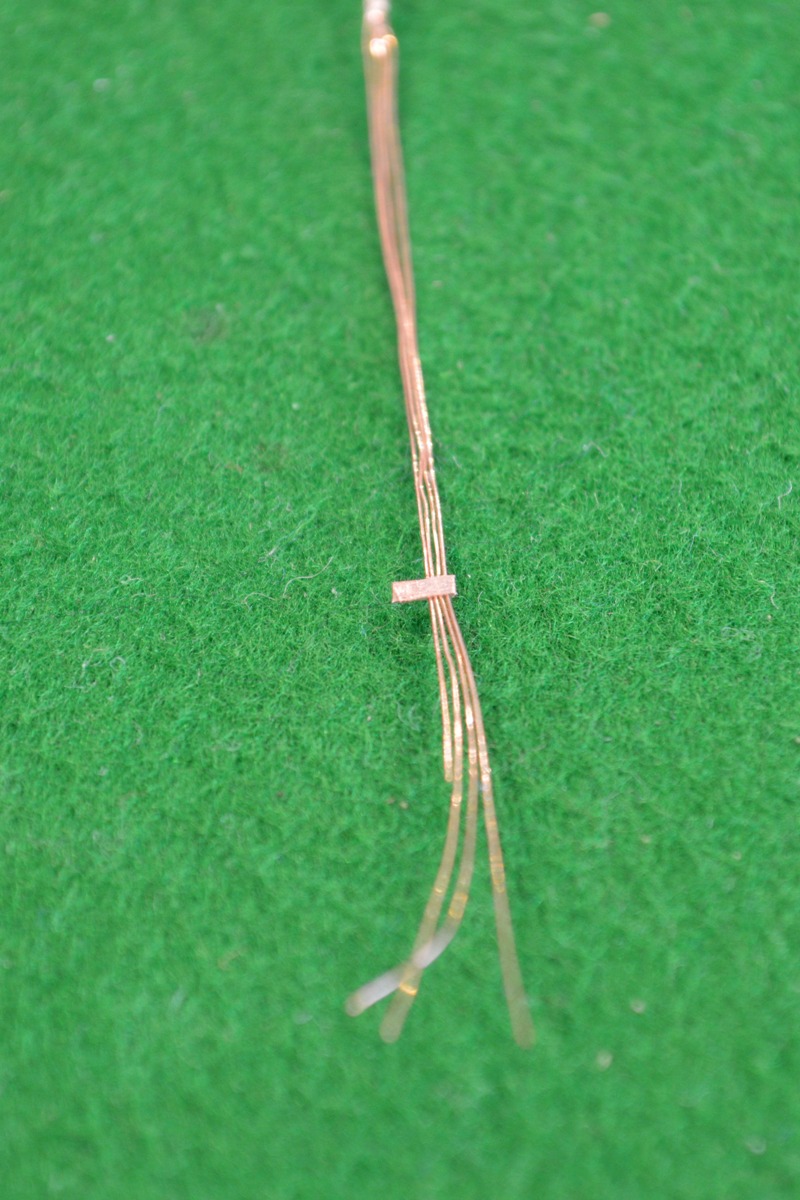
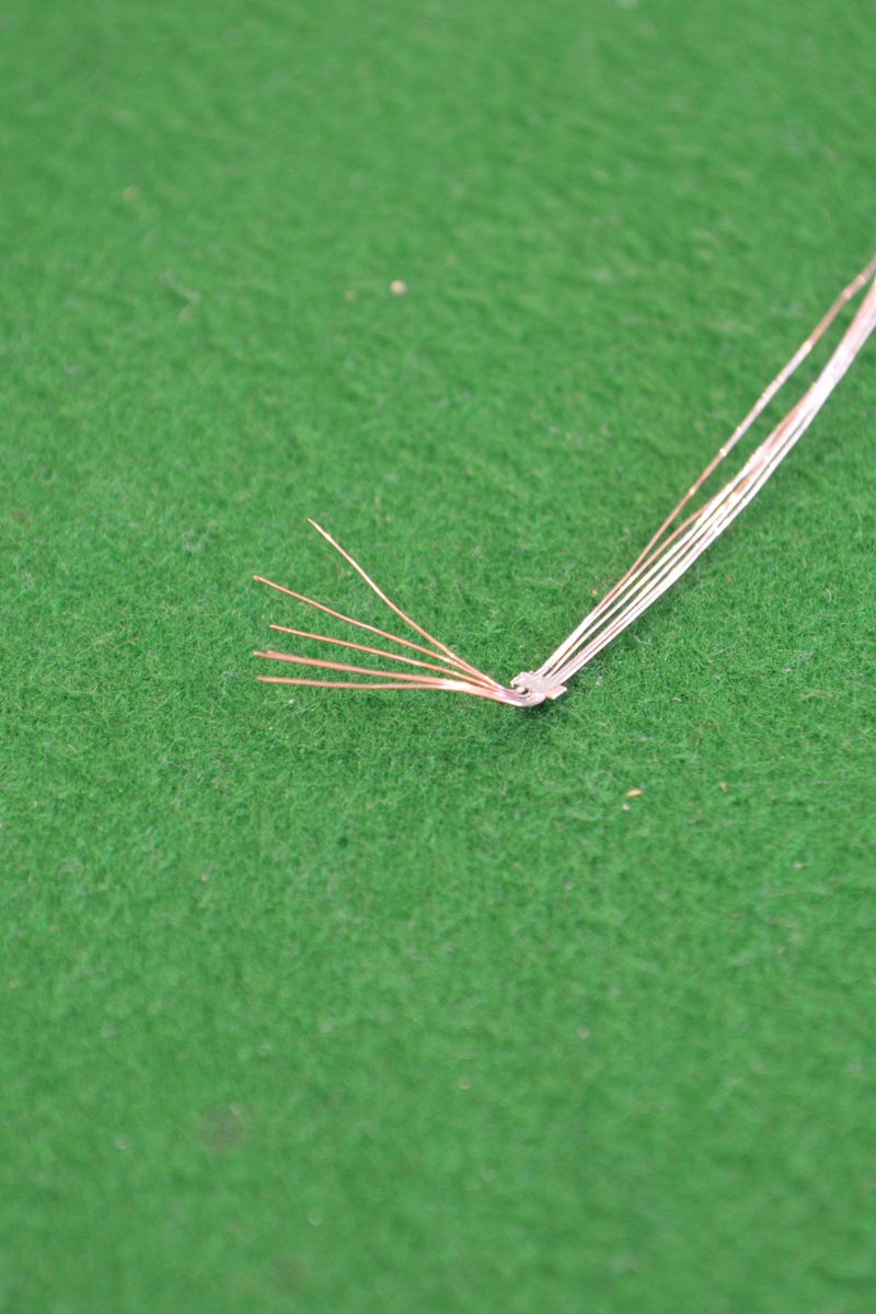
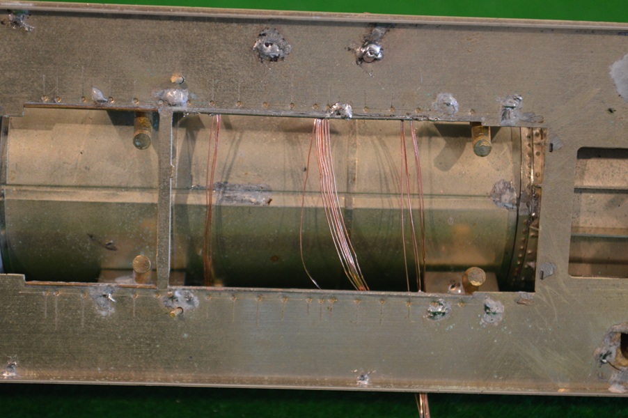
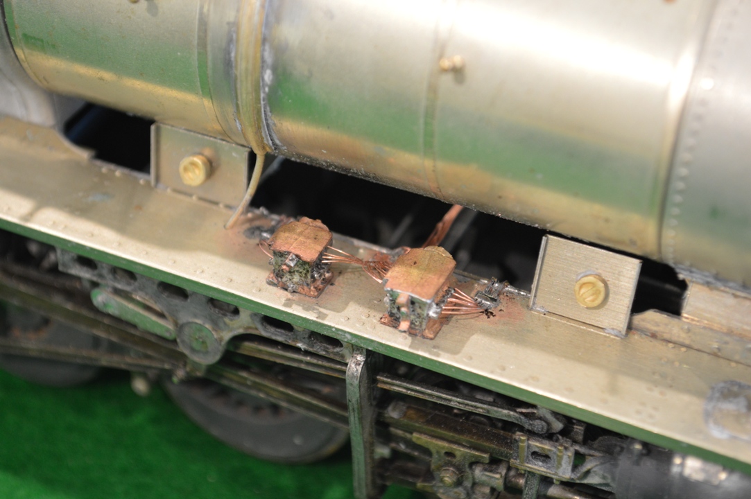
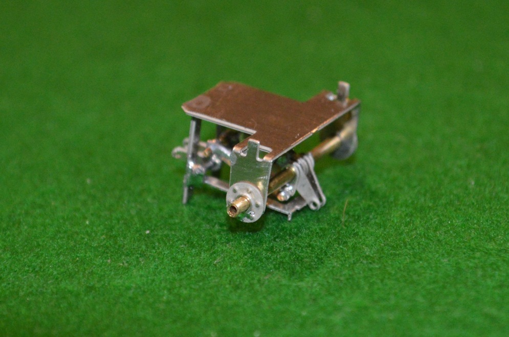
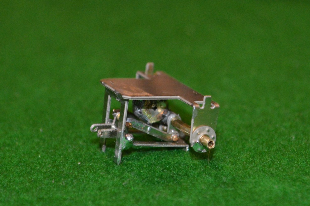
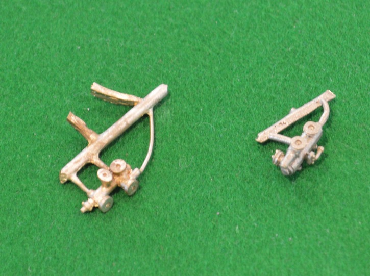
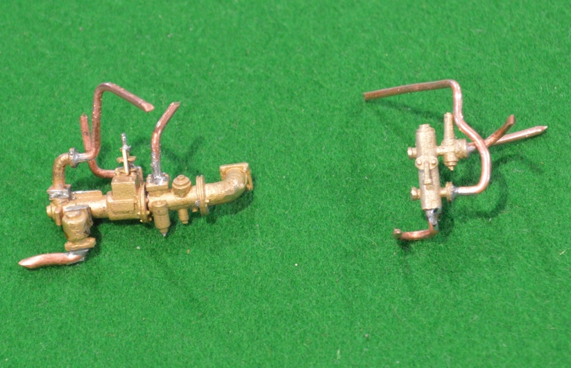
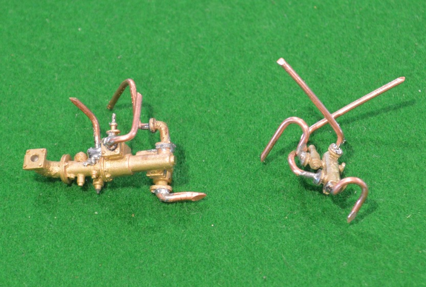
This illustrates the problem, and my solution (so far – I haven’t fully tested it yet!


The MOK kit comes with a drawbar which has a disc at one end and an elongated disc at the other (running-track shaped). Naively, I went for the close-coupled length.
It looks good, and would work well on straight track, but on curves the tender will not articulate enough with the locomotive, and one or other comes off the track. The problem was that I had cut off the extra length of the elongated end of the drawbar. So I have had to reconstruct it from flat brass strip and solder it onto the drawbar, as shown. With a slot at the tender end, I’m hoping that the tender can look realistically close to the engine itself when pushed together, but will move apart enough to go around 2m radius curves when in forward motion. We will see eventually if this works!

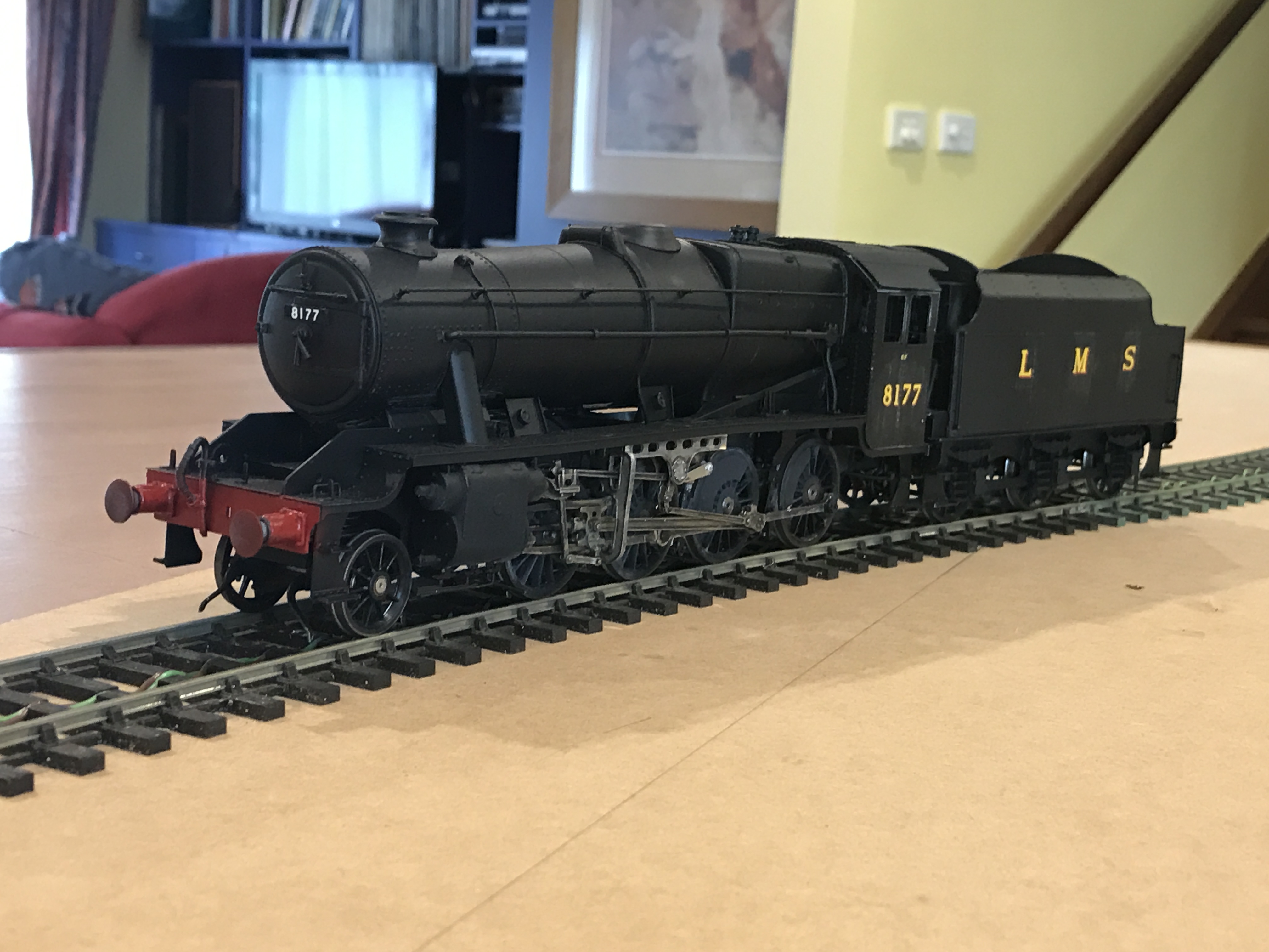
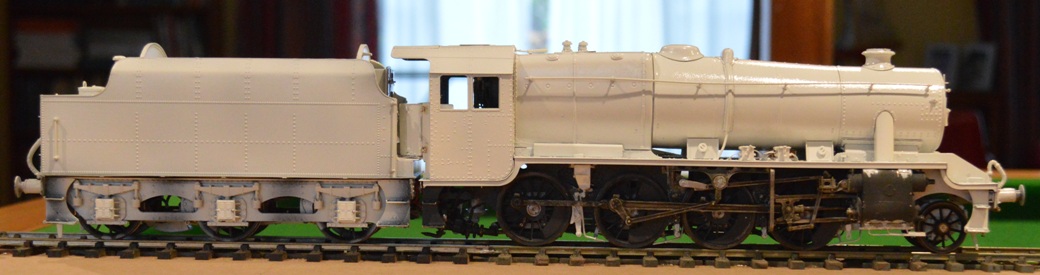
Incidentally, those who have followed this thread may notice something has changed in the pictures.  Nick and Andrew were worried that me using their pool table for pictures might end up in damage to the green baize, and so we have now constructed a wooden top for the table!   We had time for this because of our recent weather – Australia really is a different world of weather, or is it global warming?  It is still warm, but we’ve had over 150mm of rain in the 5 days, and so plenty of time for making things like table-covers – and model locomotives, of course!

Stanier 8F in ScaleSeven – Part 28: running with numbers

It still has some way to go, but the locomotive is looking more like the real thing since I added number and letters to the painting.

IMG_0428

I chose number 8177 because there is a nice photo. of this particular engine on the Settle and Carlisle railway in LMS days.

IMG_0429


I have put the transfers on and then sealed them on using water-soluble matt varnish.

Unfortunately, as can be seen, this leaves a visible stain.


IMG_0436However application of a spray-on coat of mgt varnish will remove this I think.


I have taken some videos of the locomotive moving on my test track, which I will add once they have uploaded onto YouTube (this takes literally hours!).

I still have to add the cab windows, colour the coupling hooks black and then make the engine appear more realistic with weathering.


Stanier 8F in ScaleSeven – Part 27: running in black

img_0351

This is the stage at which realism becomes more possible.  I have now painted the locomotive all over in matt black.  I will then add numbers and lettering, before applying an all-over protective coat, then add weathering to make it more realistic.

As always, click to enlarge.

As always, click to enlarge.


Here are some pictures in still and video format:


These are “Youtube” videos of the engine running on my test track.

To the educated eye there are some mistakes visible, even apart from the lack of number and lettering, but they aren’t too obvious, I hope.

There are no cab window frames or glass, some small parts remain the wrong colour (coupling hooks, etc).  No coal in the tender.

There’s also no exhaust steam injector below the left of the cab (it fell off as I was preparing the loco for the video – curses!).


Stanier 8F in ScaleSeven – Part 26: in Primer

Onto the painting!  An exciting moment.  I have put the metal primer on already.

small-primer-01

Here are a couple of pictures of the loco. and tender together.


small-primer-04The chassis and wheels have been partially painted already.

There are some modellers who assemble the entire kit before even starting to paint it, but this means that you are forced to take apart some of the construction in order to paint awkward places like behind the wheels, and so I have chosen to do a limited amount of painting as I go through.

small-primer-02small-primer-03For undercoat I use some stuff found in Australia made by a car-paint firm call Hi-Tech, who make some really good primer called (surprise) “All-Surface Primer”. I’m sure there would be equivalents made elsewhere.  Advantages are that it will stick to anything (I have to use a Stanley knife blade as a scraper to get it off the polished granite samples that we have from when we chose our benchtop in the kitchen) and that it is really thin and so easily applied by an airbrush.

I am going to have to slacken off the coupling between the tender and the locomotive, because at present there is too little movement side-to-side to allow the loco. to go around the somewhat tighter-than-realistic curves on my layout.


Stanier 8F in ScaleSeven – Part 25: build finished, prior to painting.

small-build-complete-01

I think most of the details are done, and I have put it all together.

img_0305

These are some pictures taken on my new iPhone:


img_0304


And others from the normal camera:

small-build-complete-02


small-build-complete-05 small-build-complete-06 small-build-complete-03


So for the first time, it can run as a complete locomotive:

It doesn’t run smoothly because of electrical “shorting” between the front steps and the pony truck wheels at the from, when traversing the tight curves on my test track.

.

Stanier 8F in ScaleSeven – part 23: sanding gear

We are getting to the final stages of construction now.

The details is being added to the body and the frames.  I have added much of the detail, provided by the kit manufacturer, to the body itself.  This is about adding the sanding gear.  On the prototype, this is the equipment aimed to spray sand in-between the rails and the driving wheels to improve adhesion in slippery conditions.  There are three sandboxes, with tubes going out of them down to just in front of the leading driving wheel, and both in front of and behind the third driving wheel.

In this kit there are brass castings of all three sandboxes, even though two of them are inside the frames.  The outside one goes to behind the third driving wheel and has an additional mechanism (I don”t know what function it has) beneath the sandbox itself.  The sand-delivery tubes are represented by 0.8mm nickel-silver wire bent to shape, and I made support brackets from thin strips of scrap n/s with 0.8mm holes bored in the ends, twisted and bent to shape.

small-sanding-gear-01


Here is the one for the outside sandbox, with a folded-up section of wire to represent the additional mechanism.


small-sanding-gear-03


Once bent up and soldered onto the frames, this is the (unpainted) appearance.


small-sanding-gear-02The central sandbox, supplying sand to the front of the third driving wheel, was even more of a challenge, and in the end I made wire with multiple bends in it, allowing one end to be anchored to the sandbox, with the other supported by a bracket in position near the driving wheel.

small-sanding-gear-04

This shows the course inside the frames of the central sandbox “tubing”.


This side-on view shows all the three sanding jets in place.  Of the sandboxes, only the rear one is outside the frames and visible.

small-sanding-gear-05


Stanier 8F in ScaleSeven – part 22: Mechanical lubricators and their pipes

I’m beginning to wonder just how obsessive/nerdy I can get.

On my recent visit to England (see John’s ‘blog), we travelled behind one of my beloved Stanier 8Fs on the Scarborough Spa Express.  I took pictures of the engine, and noticed many details that would be useful for my model.

Small mechanical lubricatorsAmongst these were the mechanical lubricators and their pipes.  They were all cleaned and nicely polished, and so were a quite prominent feature on the footplate of the locomotive.  In working life they would probably have been grimy and not noticeable, I suppose, but now I had seen them, I felt I had to model them accurately.


The MOK kit comes with the two lubricators, but not with the pipes which go from them.  So I had to somehow make the pipes from scratch.  Stripping some mains cable I found multi-strand copper wire with which to make the pipes.  Each strand was about 0.2mm thick, so approx. scale for a pipe 8-9mm across, which seemed about right.  However, how to make them into the beautiful fan of pipework was not obvious, to say the least.  I tried soldering the wires to the lubricator castings, but apart from clogging everything with solder, well you can imagine how successful that was.  I then tried soldering the wire strands into ribbons six wires across, intending to use lower-melt solder to attach them to the lubricators.  However I couldn’t solder the wires together over a short enough length then to make the elegant curved sections onto the castings.  Lots of burnt fingers and strained eyes.

Small MtML 07

This is how I eventually did get something approximating to the desired appearance.

Click to enlarge.


First I found some thicker copper mains cable, and flattened a section out with a hammer, evening its edges up with a file.

Small MtML 01Small MtML 02


Next I cut a small section of this cooper strip and folded it over the necessary number of strands of 0.2mm wire and hammered the folded copper strip together to hold the wire, applying a tiny amount of solder to keep it all fixed.  Then I could bend the curves into the ends of 0.2mm wire and separate them to go up to the lubricators.

Small MtML 03.Small MtML 04


Small MtML 05The one in between the two lubricators had to take ten wires/pipes, divided to go different directions, of course!

The fixing strips were then used to attach the pipes to the footplate, in a position so that the curved pipes are coming from the sides of the lubricators.

Small MtML 09The other end of the multiple-wire constructions help to hold the curved ends in place when soldering, and can then be bent into shape to represent the lubricator lines as then do down or across the chassis – a few travel across to the other side over a chassis cross-member, and are visible from above.


Small MtML 08Was it worth all the trouble?  I don’t really know, but it is satisfying to have succeeded, so if the painting eventually makes it invisible, i may just have to be content with that.


Stanier 8F in Scale Seven part 19: water scoop mechanism

I decided for some unknown reason to switch to the tender again. Perhaps because having succeeded with the brakes on the locomotive, I wanted to see if I could do them on the tender whilst the technique was still in my memory! So I measured the clearances, and found to my delight that no adjustment was really needed for ScaleSeven: the brake hangers could be soldered into the inner chassis frame and could be adjusted easily to be the correct clearance for the S7 wheels. Excellent. So I insulated the faces of the brake shoes as before, soldered the brake hangers and retried the running of the tender frames – it still works!
Next in the instructions is the water scoop lift gear. This proved to be a real challenge for me. There are times when I wish I was living in the UK (though not many ….) – the instruction sheet is really deficient in this section: “assembly is per diagrams and photos”; two unlabelled pictures and some difficult-to-decipher diagrams. It would have been much easier to be able to look at the real thing, but instead I had to look on the ‘net for drawings and pictures. It was almost too obscure even for the ubiquitous WWW: Google Images of “Stanier tender water scoop gear” produces almost no useful images!  I eventually found some useful stuff – Some pictures of a model 3500 gallon LMS tender, and most useful were pictures of the Duchess and its tender in a Birmingham museum.  I had to work out from their appearance what all the parts were for, and then how they go together.  I hope I was right.

Small Water scoop mech 001The mechanism is mounted under a crossmember of the tender chassis, and appears to be a rod or axle (moved by a long control beam from the front of the tender) on which a number of cranks are mounted. The ones at the rear end (right of photo. here) are aimed to lift the water scoop itself.

On the same axle are mounted levers which lower another device into the water troughs, the levers seen in the middle of the mech. and protruding to the left in the photo. below.
Small Water scoop mech 002
I’m not sure what this device did in real life – I guess that it was a deflector to channel more water from the edges of the water trough into the scoop?
There is also what I think must be a balance weight for the water scoop attached to the axle, seen in the middle of the mech. above (probably in the wrong position). I added to the thickness of the etched parts which represent this.
To make up the mechanism as seen above needed three parts to the frame (25 x 15 x 15mm), a piece of 1.6mm dia. rod, twelve tiny bits of etched nickel silver, half-a-dozen 1/32 brass pins and a HUGE amount of patience.

Small Water scoop mech 003Here it is in position:

Some of the brake gear is also seen, but no water scoop as yet.
If my deductions were wrong about where everything goes, I’m not sure that I really want to know ….

Stanier 8F in ScaleSeven part 18: injectors

Steam engines usually have two injectors to drive water into the boiler at high pressure.  The Stanier 8F has an “Exhaust Steam Injector” on the right under the cab, and a “Live Steam Injector” on the left.  The MOK kit has lost-wax castings of both, but the instructions are sketchy about how and exactly where to put them.  When I looked at the engineers drawings, it became obvious that the live steam injector molding was incorrect.  There should be four pipes coming off it or going to it.  Water supply above the outgoing water to the boiler, on the inside surface, Live steam supply at the front, and overflow at the back.  The MOK molding had four places for pipes, but two were on the side and two on the rear.  In looking on the ‘net I had found illustrations of the injectors, and information that Laurie Griffin manufactures very good castings of both exhaust and live steam injectors, so I bought some by mail order.

MOK casting on left, Laurie Griffin on right

MOK casting on left, Laurie Griffin on right


When they arrived they were clearly a great improvement on the MOK ones in terms of detail, but the Laurie Griffin one was wrong also!  The LG live steam injector only had three pipe fittings!

The LG one looks better, so I have used that one, fitting the overflow pipe to the bottom of the injector.


Small Frames with old injectorWhen I had put the exhaust steam injector onto the frames it involved fitting the steam pipe from the cylinders.  It is difficult to form the reverse bend at the rear of the locomotive, and I hadn’t bent it quite correctly, leaving the pipe running at an angle down the frames.

The Laurie Griffin exhaust injector molding includes last bend of this pipe, so it gave me an opportunity to correct this error.

However the injector comes in five pieces, which need to be soldered together, and then the four pipes have to be soldered onto the injector, without any of the other joints becoming un-soldered!  It took me all day today, but here are the final results:

Small Both injectors with pipes 2.Small Both injectors with pipes


Click to enlarge.  Clearly they have yet to go in place, but I might paint them first – it will be difficult after they are fitted.  The Laurie Griffin exhaust steam injector (on the left in both pictures above) has exquisite detail, so I don’t want to mess it up with a poor paint job.